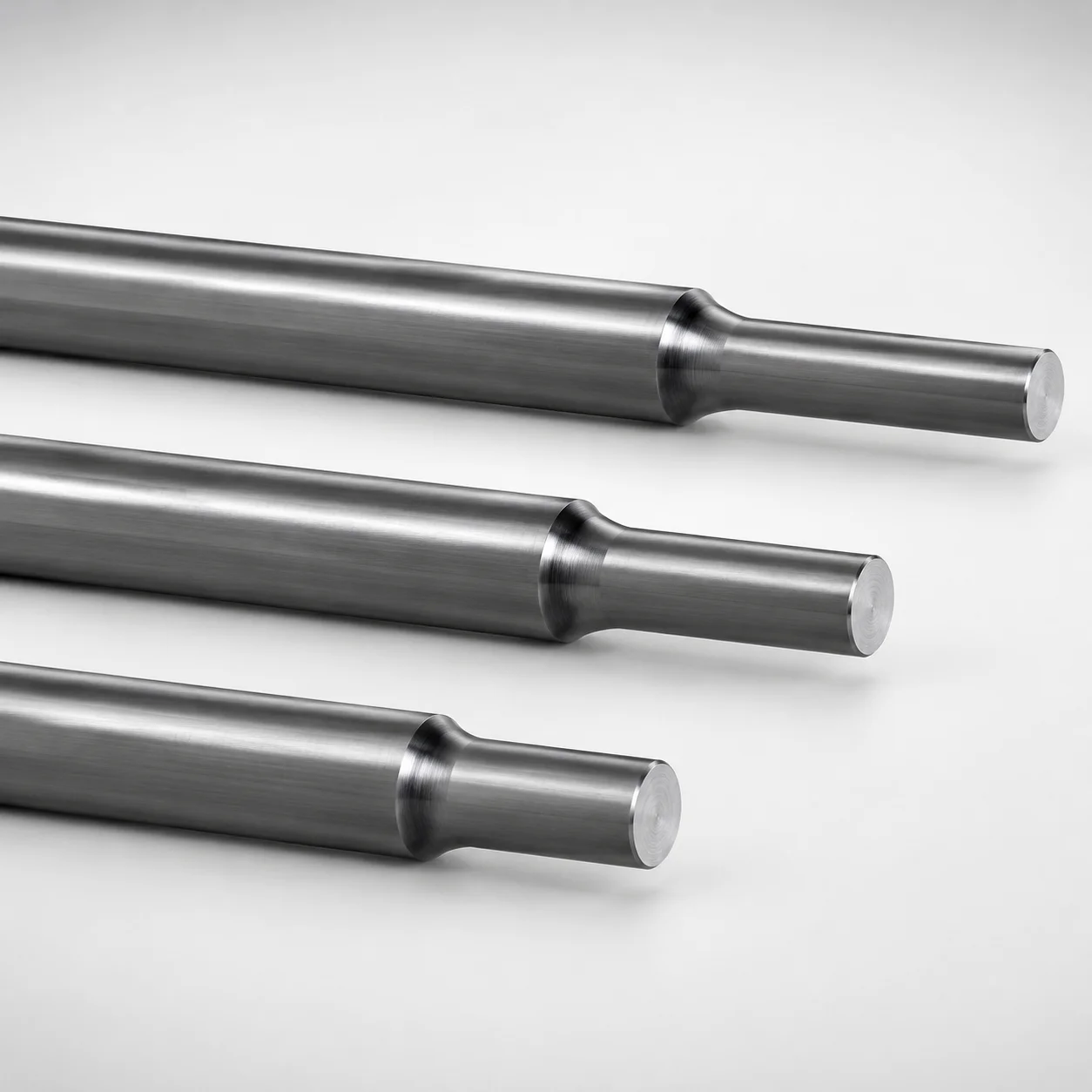
JIS Standard SKD61 Steel Stepped Ejector Pins with Concave Engraving
Stepped ejector pins with concave engraving (SKD61 steel) are designed for stable ejection in precision molds, combining a stepped shaft profile with a controlled engraved character finish. The nitrided surface helps support long-term wear resistance in production.
- Stepped pin geometry for consistent guidance during ejection cycles
- Nitrided SKD61 steel improves wear resistance for demanding runs
- Supports tight fit control with tip and shaft tolerance references of -0.01/-0.02 and 0/-0.02
- JIS head configuration with WOS engraving designation for standard mold integration
Specifications
89 configurations available
| Tip Diameter Tolerance Reference | Head Thickness | D (Shaft Diameter) (mm) | P (Tip Diameter) (mm) | Number of Outer Ring Characters | L (L dimension) (mm) | Dimension N (mm) | Engraving character designation | type |
|---|---|---|---|---|---|---|---|---|
| -0.01/-0.02 | 6mm(JIS) | 4 | 1.5 ~ 3.9 | 1 characters | 50 ~ 300 | 13 ~ 290 | ※Designation by WOS | - |
| -0.01/-0.02 | 6mm(JIS) | 4.5 | 2.5 ~ 4.4 | 1 characters | 50 ~ 300 | 13 ~ 290 | ※Designation by WOS | - |
| -0.01/-0.02 | 6mm(JIS) | 5 | 3 ~ 4.9 | 1 characters | 50 ~ 300 | 13 ~ 290 | ※Designation by WOS | - |
| -0.01/-0.02 | 6mm(JIS) | 5.5 | 3.5 ~ 5.4 | 1 characters | 50 ~ 300 | 13 ~ 290 | ※Designation by WOS | - |
| -0.01/-0.02 | 6mm(JIS) | 6 | 4 ~ 5.9 | 1 characters | 50 ~ 300 | 13 ~ 290 | ※Designation by WOS | - |
| -0.01/-0.02 | 6mm(JIS) | 6.5 | 4.5 ~ 6.4 | 1 characters | 50 ~ 300 | 13 ~ 290 | ※Designation by WOS | - |
| -0.01/-0.02 | 6mm(JIS) | 7 | 4.9 ~ 6.9 | 1 characters | 50 ~ 300 | 13 ~ 290 | ※Designation by WOS | - |
| -0.01/-0.02 | 8mm(JIS) | 8 | 5.9 ~ 7.9 | 1 characters | 50 ~ 300 | 13 ~ 290 | ※Designation by WOS | - |
| - | 8mm(JIS) | 10 | 7.9 ~ 9.9 | 1 characters | 50 ~ 300 | 13 ~ 290 | ※Designation by WOS | - |
| - | 8mm(JIS) | 12 | 8.9 ~ 11.9 | 1 characters | 50 ~ 300 | 13 ~ 290 | ※Designation by WOS | - |
| - | 8mm(JIS) | 15 | 10.9 ~ 14.9 | 1 characters | 50 ~ 300 | 13 ~ 290 | ※Designation by WOS | - |
| - | 8mm(JIS) | 16 | 11.9 ~ 15.9 | 1 characters | 50 ~ 300 | 13 ~ 290 | ※Designation by WOS | - |
| - | 8mm(JIS) | 20 | 15.9 ~ 19.9 | 1 characters | 50 ~ 300 | 13 ~ 290 | ※Designation by WOS | - |
| -0.01/-0.02 | 6mm(JIS) | 4 | 1.5 ~ 3.9 | 1 characters | 50 ~ 300 | 13 ~ 290 | ※Designation by WOS | - |
| -0.01/-0.02 | 6mm(JIS) | 4.5 | 2.5 ~ 4.4 | 1 characters | 50 ~ 300 | 13 ~ 290 | ※Designation by WOS | - |
| -0.01/-0.02 | 6mm(JIS) | 5 | 3 ~ 4.9 | 1 characters | 50 ~ 300 | 13 ~ 290 | ※Designation by WOS | - |
| -0.01/-0.02 | 6mm(JIS) | 5.5 | 3.5 ~ 5.4 | 1 characters | 50 ~ 300 | 13 ~ 290 | ※Designation by WOS | - |
| -0.01/-0.02 | 6mm(JIS) | 6 | 4 ~ 5.9 | 1 characters | 50 ~ 300 | 13 ~ 290 | ※Designation by WOS | - |
| -0.01/-0.02 | 6mm(JIS) | 6.5 | 4.5 ~ 6.4 | 1 characters | 50 ~ 300 | 13 ~ 290 | ※Designation by WOS | - |
| -0.01/-0.02 | 6mm(JIS) | 7 | 4.9 ~ 6.9 | 1 characters | 50 ~ 300 | 13 ~ 290 | ※Designation by WOS | - |
| -0.01/-0.02 | 8mm(JIS) | 8 | 5.9 ~ 7.9 | 1 characters | 50 ~ 300 | 13 ~ 290 | ※Designation by WOS | - |
| - | 8mm(JIS) | 10 | 7.9 ~ 9.9 | 1 characters | 50 ~ 300 | 13 ~ 290 | ※Designation by WOS | - |
| - | 8mm(JIS) | 12 | 8.9 ~ 11.9 | 1 characters | 50 ~ 300 | 13 ~ 290 | ※Designation by WOS | - |
| - | 8mm(JIS) | 15 | 10.9 ~ 14.9 | 1 characters | 50 ~ 300 | 13 ~ 290 | ※Designation by WOS | - |
| - | 8mm(JIS) | 16 | 11.9 ~ 15.9 | 1 characters | 50 ~ 300 | 13 ~ 290 | ※Designation by WOS | - |
| - | 8mm(JIS) | 20 | 15.9 ~ 19.9 | 1 characters | 50 ~ 300 | 13 ~ 290 | ※Designation by WOS | - |
| -0.01/-0.02 | 6mm(JIS) | 4 | 1.5 ~ 3.9 | 2 characters | 50 ~ 300 | 13 ~ 290 | ※Designation by WOS | - |
| -0.01/-0.02 | 6mm(JIS) | 4.5 | 2.5 ~ 4.4 | 2 characters | 50 ~ 300 | 13 ~ 290 | ※Designation by WOS | - |
| -0.01/-0.02 | 6mm(JIS) | 5 | 3 ~ 4.9 | 2 characters | 50 ~ 300 | 13 ~ 290 | ※Designation by WOS | - |
| -0.01/-0.02 | 6mm(JIS) | 5.5 | 3.5 ~ 5.4 | 2 characters | 50 ~ 300 | 13 ~ 290 | ※Designation by WOS | - |
| -0.01/-0.02 | 6mm(JIS) | 6 | 4 ~ 5.9 | 2 characters | 50 ~ 300 | 13 ~ 290 | ※Designation by WOS | - |
| -0.01/-0.02 | 6mm(JIS) | 6.5 | 4.5 ~ 6.4 | 2 characters | 50 ~ 300 | 13 ~ 290 | ※Designation by WOS | - |
| -0.01/-0.02 | 6mm(JIS) | 7 | 4.9 ~ 6.9 | 2 characters | 50 ~ 300 | 13 ~ 290 | ※Designation by WOS | - |
| -0.01/-0.02 | 8mm(JIS) | 8 | 5.9 ~ 7.9 | 2 characters | 50 ~ 300 | 13 ~ 290 | ※Designation by WOS | - |
| - | 8mm(JIS) | 10 | 7.9 ~ 9.9 | 2 characters | 50 ~ 300 | 13 ~ 290 | ※Designation by WOS | - |
| - | 8mm(JIS) | 12 | 8.9 ~ 11.9 | 2 characters | 50 ~ 300 | 13 ~ 290 | ※Designation by WOS | - |
| - | 8mm(JIS) | 15 | 10.9 ~ 14.9 | 2 characters | 50 ~ 300 | 13 ~ 290 | ※Designation by WOS | - |
| - | 8mm(JIS) | 16 | 11.9 ~ 15.9 | 2 characters | 50 ~ 300 | 13 ~ 290 | ※Designation by WOS | - |
| - | 8mm(JIS) | 20 | 15.9 ~ 19.9 | 2 characters | 50 ~ 300 | 13 ~ 290 | ※Designation by WOS | - |
| -0.01/-0.02 | 6mm(JIS) | 4 | 1.5 ~ 3.9 | 2 characters | 50 ~ 300 | 13 ~ 290 | ※Designation by WOS | - |
| -0.01/-0.02 | 6mm(JIS) | 4.5 | 2.5 ~ 4.4 | 2 characters | 50 ~ 300 | 13 ~ 290 | ※Designation by WOS | - |
| -0.01/-0.02 | 6mm(JIS) | 5 | 3 ~ 4.9 | 2 characters | 50 ~ 300 | 13 ~ 290 | ※Designation by WOS | - |
| -0.01/-0.02 | 6mm(JIS) | 5.5 | 3.5 ~ 5.4 | 2 characters | 50 ~ 300 | 13 ~ 290 | ※Designation by WOS | - |
| -0.01/-0.02 | 6mm(JIS) | 6 | 4 ~ 5.9 | 2 characters | 50 ~ 300 | 13 ~ 290 | ※Designation by WOS | - |
| -0.01/-0.02 | 6mm(JIS) | 6.5 | 4.5 ~ 6.4 | 2 characters | 50 ~ 300 | 13 ~ 290 | ※Designation by WOS | - |
| -0.01/-0.02 | 6mm(JIS) | 7 | 4.9 ~ 6.9 | 2 characters | 50 ~ 300 | 13 ~ 290 | ※Designation by WOS | - |
| -0.01/-0.02 | 8mm(JIS) | 8 | 5.9 ~ 7.9 | 2 characters | 50 ~ 300 | 13 ~ 290 | ※Designation by WOS | - |
| - | 8mm(JIS) | 10 | 7.9 ~ 9.9 | 2 characters | 50 ~ 300 | 13 ~ 290 | ※Designation by WOS | - |
| - | 8mm(JIS) | 12 | 8.9 ~ 11.9 | 2 characters | 50 ~ 300 | 13 ~ 290 | ※Designation by WOS | - |
| - | 8mm(JIS) | 15 | 10.9 ~ 14.9 | 2 characters | 50 ~ 300 | 13 ~ 290 | ※Designation by WOS | - |
Product Guide
Application Scenarios+
These stepped ejector pins are used in injection mold tooling where controlled ejection, long cycle stability, and durable tip geometry are required. The stepped shaft profile provides better guidance through the ejector stroke, helping maintain alignment during repetitive opening and closing.
- Automotive connector and bracket molds: Suitable for producing housings and insert features that demand reliable ejection without galling; the nitrided SKD61 surface treatment supports wear resistance in high-volume production.
- Electronics enclosure molds: The concave character engraving designation supports consistent feature formation while benefiting from a wear-resistant surface for clean ejection over long runs.
- General precision molds with tight fit control: The provided tip diameter tolerance references (e.g., -0.01/-0.02 and 0/-0.02) support stable tip-to-hole fit, reducing variance in ejection force and preventing excess play.
With JIS configuration and WOS engraving designation, this variant aligns with standard integration practices for mold builders and component replacement.
Material & Process Details+
This product uses JIS Standard SKD61 steel, commonly aligned with AISI H13-equivalent applications for hot-work tooling due to its balance of hardenability, toughness, and wear performance. The meta description specifies a nitrided surface treatment, which enhances surface hardness and abrasion resistance while preserving core toughness.
- Nitrided surface: Improves wear resistance at the ejector tip where sliding/contact occurs, supporting durability during high-cycle ejection.
- Hardness trade-off: Nitriding primarily strengthens the surface; core properties still rely on the SKD61 heat-treatment condition to maintain impact resistance under load.
- Heat treatment (typical for SKD61 families): Quenched and tempered steel is commonly used as the base before nitriding, then the nitrided layer provides the near-surface wear improvement.
If comparing alternatives, tool steels without nitriding generally offer less surface abrasion resistance, while higher-alloy wear steels may improve surface durability but can increase cost and complicate heat treatment control.
Sizing & Selection Guide+
Select dimensions by matching the ejector-pin geometry to the mold’s ejector layout and the required fit at the moving interfaces. This series provides a shaft diameter (D) range of 4 ~ 20 mm and a tip diameter (P) range of 1.5 ~ 15.9 mm. Choose the L length from 50 ~ 300 mm to ensure full travel coverage and proper clearance through guide components.
- Tip diameter / fit: Use the fixed tip diameter tolerance reference -0.01/-0.02 and 0/-0.02 when calculating pin-to-bore clearance. For tight fits, confirm the mating hole tolerance and surface finish to maintain stable ejection force.
- Head thickness: Head thickness is variable in 6 mm (JIS) or 8 mm (JIS); select the value that matches your ejector plate thickness and retention design.
- Engraving designation: Character marking follows WOS designation, with outer ring character counts from 1 to 5 characters.
Finally, confirm fixed geometry values such as N (13 ~ 290 mm) to ensure correct stack-up with your mold’s mechanical stop and support structure.
Frequently Asked Questions
How do I select the correct shaft diameter D for this stepped ejector pin series (4–20 mm)?+
What tip diameter tolerance references are applicable for P, and how should they affect clearance design?+
Is the nitrided surface treatment included, and what wear areas benefit most?+
How do I choose between JIS head thickness 6 mm and 8 mm for the ejector plate?+
What does the WOS concave engraving designation imply for compatibility with character-bearing mold features?+
Related Products
Need Custom Specifications?
Our engineering team can help with custom configurations, material selection, and volume pricing.