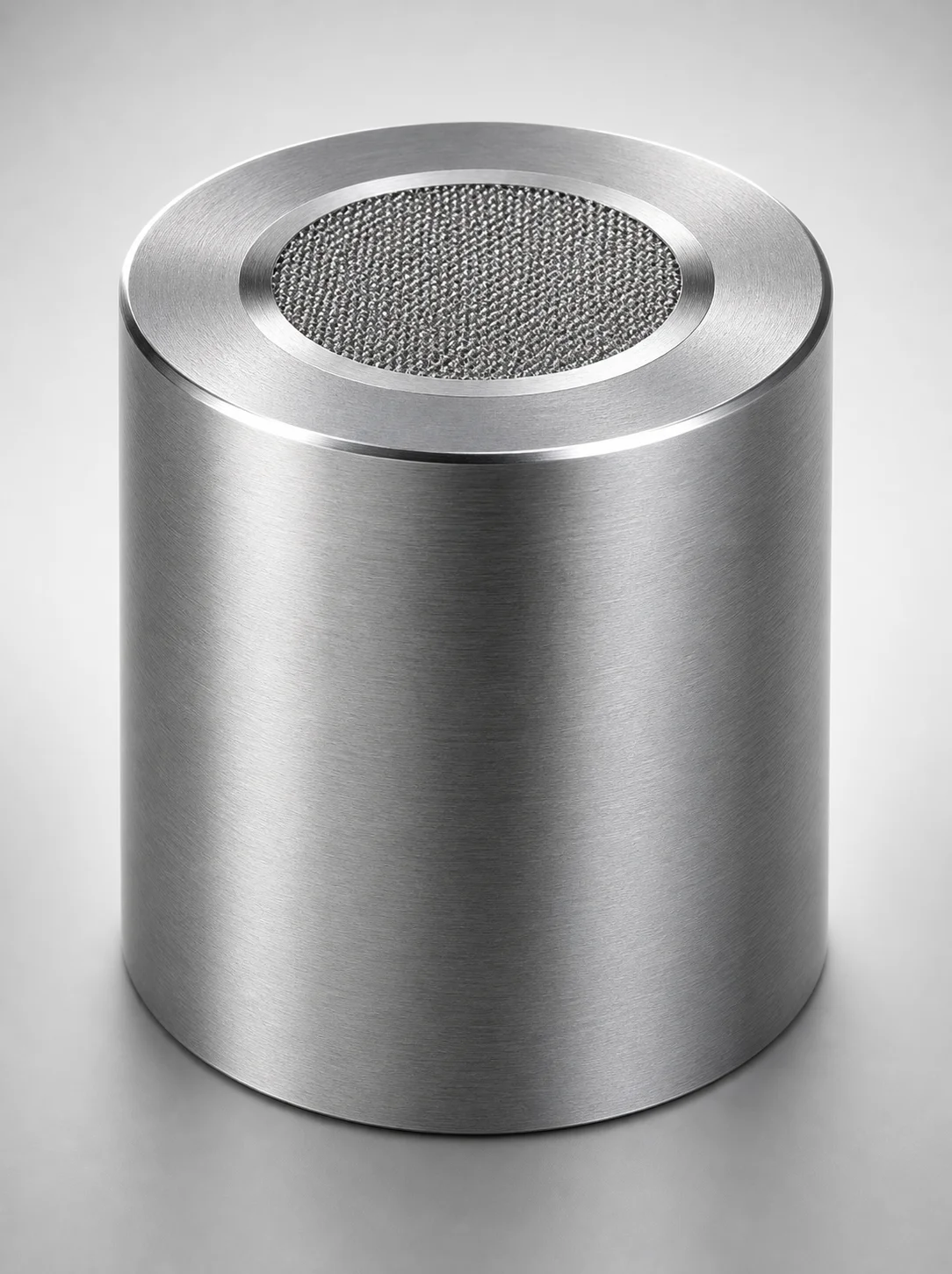
Stainless Steel Gas Vent Round Inserts
Stainless Steel gas vent round inserts are built for reliable pressure relief by releasing excess gas through an integrated round insert configuration. They help maintain stable process conditions and reduce risk from gas buildup.
- Round insert gas venting design supports efficient gas vent for pressure control
- Stainless steel construction offers corrosion resistance for industrial environments
- Designed for consistent fitting across insert outer diameter and hole diameter options
- Suitable for tool and equipment assemblies requiring controlled gas release
Specifications
21 configurations available
| D (Outer diameter) (mm) | Hole Diameter (mm) | type |
|---|---|---|
| 2 | 0.03 | - |
| 3 | 0.03 | - |
| 4 | 0.03 | - |
| 6 | 0.03 | - |
| 2 | 0.05 | - |
| 3 | 0.05 | - |
| 4 | 0.05 | - |
| 6 | 0.05 | - |
| 8 | 0.05 | - |
| 10 | 0.05 | - |
| 2 | 0.1 | - |
| 3 | 0.1 | - |
| 5 | 0.1 | - |
| 6 | 0.1 | - |
| 8 | 0.1 | - |
| 10 | 0.1 | - |
| 6 | 0.2 | - |
| 8 | 0.2 | - |
| 2 | 0.02 | - |
| 3 | 0.02 | - |
| 4 | 0.02 | - |
Product Guide
Application Scenarios+
These round gas vent inserts are used in injection mold tooling wherever trapped air or volatiles must be released to stabilize filling and prevent surface defects. Typical scenario 1: automotive interior and under-hood component molds benefit from controlled gas venting near parting lines to reduce burn marks and gas traps, improving dimensional stability during high-cycle production.
Typical scenario 2: electronics and appliance housings often require consistent venting at small interfaces. The round insert layout supports an efficient pressure-relief path, helping the mold maintain repeatable cavity pressure and flow behavior.
Typical scenario 3: medical device housing molds and other precision products can use the stainless steel variant for corrosive-prone environments, such as cleaning cycles with aqueous solutions. The stainless steel construction is well-suited for long tool life where corrosion resistance matters.
- Best suited for gas-release units that match insert outer diameter (D) and selected hole diameter for your vent flow requirement.
- Compatible with tool/equipment assemblies needing stable, controlled gas release.
Material & Process Details+
The stainless steel gas vent insert is selected for its corrosion resistance in industrial mold environments, helping preserve vent performance during repeated cycles and cleaning. While the provided specifications confirm stainless steel construction, this variant’s exact grade, hardness (HRC), and heat-treatment state are not specified in the data set, so they should be confirmed from the product’s material certification before hardness-critical designs.
- Property focus: corrosion resistance and dimensional stability around small vent features (hole diameters as low as 0.02–0.2 mm).
- Manufacturing relevance: the micro-hole geometry typically requires precision machining or controlled forming followed by polishing/finishing to maintain vent consistency.
- Trade-offs: compared with tool steels used for wear-heavy cores, stainless steel prioritizes chemical resistance; extreme wear resistance and high-HRC performance may be lower depending on the specific grade.
If you can share the intended steel grade for this series, hardness and heat treatment (e.g., solution anneal, quench & temper, nitriding) can be mapped precisely to your wear/corrosion requirements.
Sizing & Selection Guide+
Correct vent sizing ensures the insert releases gas without causing flash, jetting, or unacceptable cavity pressure loss. Select the insert D (outer diameter) first, then match the hole diameter to your required vent flow rate for the specific cavity geometry.
- Outer diameter D: choose from 2 to 10 mm to fit the intended vent pocket/receiving feature in your gas-release unit assembly.
- Hole diameter: select from 0.02, 0.03, 0.05, 0.1, 0.2 mm based on how aggressively you must relieve trapped gas while maintaining surface finish and part appearance.
When matching to mold cavity/core requirements, ensure the pocket dimensions accommodate the selected D with appropriate clearance for assembly and any retaining hardware. Because the provided data does not list explicit tolerances, treat hole diameters as precision features and verify fit/clearance through drawings or incoming inspection (especially for 0.02–0.05 mm holes).
Note: D and hole diameter are configurable within the stated ranges; other attributes (material construction) are fixed to the stainless steel variant for this series.
Frequently Asked Questions
How do I choose the insert outer diameter D (2–10 mm) for my gas vent pocket?+
What hole diameter options are available, and how do they affect venting performance?+
Can this stainless steel vent insert be used in corrosive or frequent-cleaning environments?+
What tolerances should I assume for the 0.02–0.2 mm vent holes?+
Is the insert size more constrained by the outer diameter D or the hole diameter?+
Related Products
Need Custom Specifications?
Our engineering team can help with custom configurations, material selection, and volume pricing.