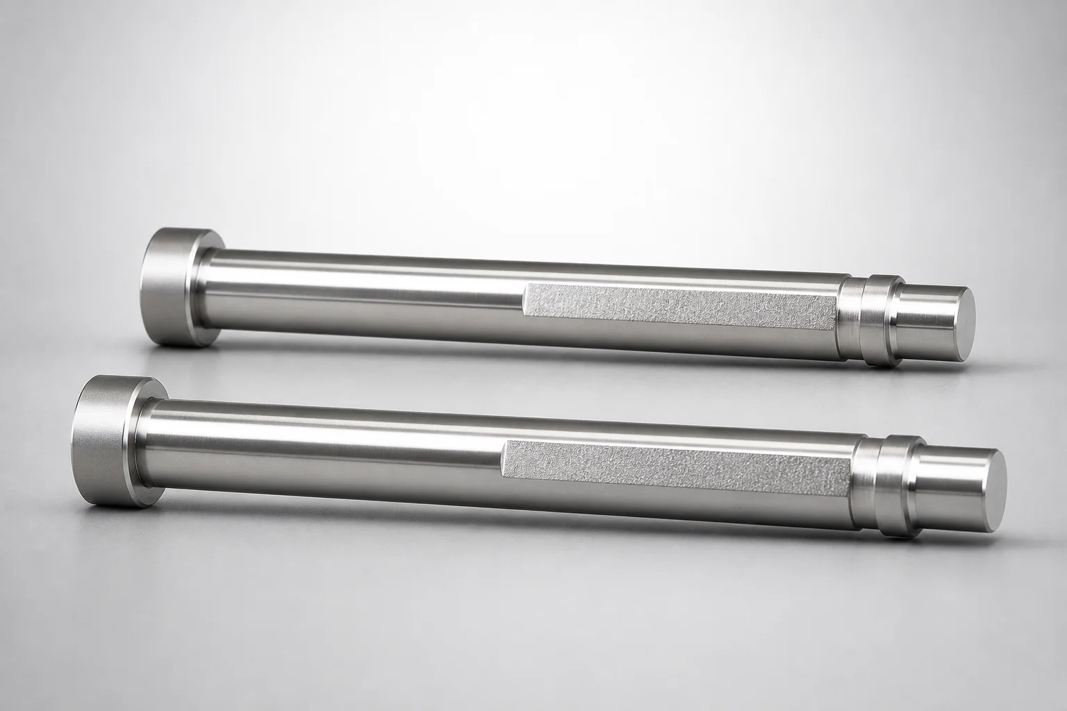
DIN Standard SKH51 Steel Gas Release Taperless One-Step Core Pins Flat-Svc
Gas release taperless one-step core pins (SKH51 steel) are designed for efficient mold venting with a one-step configuration and an extended anti-rotation flat that reaches the pin bottom for consistent core support. The taperless form helps maintain reliable alignment through repeated production cycles.
- Flat-Svc extended flat section improves anti-rotation control and stable seating in the core
- SKH51 steel quenched and hardened for strong wear resistance in high-cycle tooling
- One-step gas-release geometry supports controlled venting to help reduce trapped air effects
- Built to DIN standard requirements for compatibility with typical mold core layouts
Specifications
19200 configurations available
| Material | L Dimension Tolerance | Tip Gradient Tolerance | A/AAC (Tip Diameter) (mm) | D/P (Shaft Diameter) (mm) | First Step Shape | Tip Shape | RE (R shape alteration・enlargement) (mm) | C (Step type taper width) (mm) | CVC (C dimension can be designated at 0.01mm increments) (mm) | DC (Gas release section diameter) (mm) | Extend the flat section SV to the bottom | F (Bearing bore length) (mm) | FC (Makes F dimension shorter than F min) (mm) | G (Tip C chamfering width) (mm) | K (Tip angle) (°) | L (L dimension) (mm) | N (Gas release section diameter) (mm) | Q (Tip R chamfering) (mm) | R (Step type R) (mm) | S (Tip tapered width) (mm) | SV (Gas release facet cutting length) (mm) | When DC = D, DCX is applied | type |
|---|---|---|---|---|---|---|---|---|---|---|---|---|---|---|---|---|---|---|---|---|---|---|---|
| SKH51 | 0/-0.05 | 0/-0.01 | 0.5 ~ 0.99 | 1 | B | B | - | - | - | 0.92 ~ 0.995 | - | 14.5 ~ 99.35 | - | - | - | 16.5 ~ 100 | 0.3 ~ 10 | - | - | - | 2 ~ 50 | - | - |
| SKH51 | 0/-0.05 | 0/-0.01 | 0.5 ~ 0.99 | 1 | B | B | - | - | - | 0.92 ~ 0.995 | SVC | 14.5 ~ 99.35 | - | - | - | 16.5 ~ 100 | 0.3 ~ 10 | - | - | - | - | - | - |
| SKH51 | 0/-0.05 | 0/-0.01 | 0.5 ~ 0.99 | 1 | B | B | - | - | - | - | - | 14.5 ~ 99.35 | - | - | - | 16.5 ~ 100 | 0.3 ~ 10 | - | - | - | 2 ~ 50 | DCX | - |
| SKH51 | 0/-0.05 | 0/-0.01 | 0.5 ~ 0.99 | 1 | B | B | - | - | - | - | SVC | 14.5 ~ 99.35 | - | - | - | 16.5 ~ 100 | 0.3 ~ 10 | - | - | - | - | DCX | - |
| SKH51 | 0/-0.05 | 0/-0.01 | 0.4 ~ 0.49 | 1 | B | B | - | - | - | 0.92 ~ 0.995 | - | 14.5 ~ 99.35 | - | - | - | 16.5 ~ 100 | 0.3 ~ 10 | - | - | - | 2 ~ 50 | - | - |
| SKH51 | 0/-0.05 | 0/-0.01 | 0.4 ~ 0.49 | 1 | B | B | - | - | - | 0.92 ~ 0.995 | SVC | 14.5 ~ 99.35 | - | - | - | 16.5 ~ 100 | 0.3 ~ 10 | - | - | - | - | - | - |
| SKH51 | 0/-0.05 | 0/-0.01 | 0.4 ~ 0.49 | 1 | B | B | - | - | - | - | - | 14.5 ~ 99.35 | - | - | - | 16.5 ~ 100 | 0.3 ~ 10 | - | - | - | 2 ~ 50 | DCX | - |
| SKH51 | 0/-0.05 | 0/-0.01 | 0.4 ~ 0.49 | 1 | B | B | - | - | - | - | SVC | 14.5 ~ 99.35 | - | - | - | 16.5 ~ 100 | 0.3 ~ 10 | - | - | - | - | DCX | - |
| SKH51 | 0/-0.05 | 0/-0.01 | 0.5 ~ 1.49 | 1.5 | B | B | - | - | - | 1.42 ~ 1.495 | - | 14.5 ~ 99.35 | - | - | - | 16.5 ~ 100 | 0.3 ~ 10 | - | - | - | 2 ~ 50 | - | - |
| SKH51 | 0/-0.05 | 0/-0.01 | 0.5 ~ 1.49 | 1.5 | B | B | - | - | - | 1.42 ~ 1.495 | SVC | 14.5 ~ 99.35 | - | - | - | 16.5 ~ 100 | 0.3 ~ 10 | - | - | - | - | - | - |
| SKH51 | 0/-0.05 | 0/-0.01 | 0.5 ~ 1.49 | 1.5 | B | B | - | - | - | - | - | 14.5 ~ 99.35 | - | - | - | 16.5 ~ 100 | 0.3 ~ 10 | - | - | - | 2 ~ 50 | DCX | - |
| SKH51 | 0/-0.05 | 0/-0.01 | 0.5 ~ 1.49 | 1.5 | B | B | - | - | - | - | SVC | 14.5 ~ 99.35 | - | - | - | 16.5 ~ 100 | 0.3 ~ 10 | - | - | - | - | DCX | - |
| SKH51 | 0/-0.05 | 0/-0.01 | 0.4 ~ 0.49 | 1.5 | B | B | - | - | - | 1.42 ~ 1.495 | - | 14.5 ~ 99.35 | - | - | - | 16.5 ~ 100 | 0.3 ~ 10 | - | - | - | 2 ~ 50 | - | - |
| SKH51 | 0/-0.05 | 0/-0.01 | 0.4 ~ 0.49 | 1.5 | B | B | - | - | - | 1.42 ~ 1.495 | SVC | 14.5 ~ 99.35 | - | - | - | 16.5 ~ 100 | 0.3 ~ 10 | - | - | - | - | - | - |
| SKH51 | 0/-0.05 | 0/-0.01 | 0.4 ~ 0.49 | 1.5 | B | B | - | - | - | - | - | 14.5 ~ 99.35 | - | - | - | 16.5 ~ 100 | 0.3 ~ 10 | - | - | - | 2 ~ 50 | DCX | - |
| SKH51 | 0/-0.05 | 0/-0.01 | 0.4 ~ 0.49 | 1.5 | B | B | - | - | - | - | SVC | 14.5 ~ 99.35 | - | - | - | 16.5 ~ 100 | 0.3 ~ 10 | - | - | - | - | DCX | - |
| SKH51 | 0/-0.05 | 0/-0.01 | 0.5 ~ 1.99 | 2 | B | B | - | - | - | 1.92 ~ 1.995 | - | 14.5 ~ 99.35 | - | - | - | 16.5 ~ 100 | 0.3 ~ 10 | - | - | - | 2 ~ 50 | - | - |
| SKH51 | 0/-0.05 | 0/-0.01 | 0.5 ~ 1.99 | 2 | B | B | - | - | - | 1.92 ~ 1.995 | SVC | 14.5 ~ 99.35 | - | - | - | 16.5 ~ 100 | 0.3 ~ 10 | - | - | - | - | - | - |
| SKH51 | 0/-0.05 | 0/-0.01 | 0.5 ~ 1.99 | 2 | B | B | - | - | - | - | - | 14.5 ~ 99.35 | - | - | - | 16.5 ~ 100 | 0.3 ~ 10 | - | - | - | 2 ~ 50 | DCX | - |
| SKH51 | 0/-0.05 | 0/-0.01 | 0.5 ~ 1.99 | 2 | B | B | - | - | - | - | SVC | 14.5 ~ 99.35 | - | - | - | 16.5 ~ 100 | 0.3 ~ 10 | - | - | - | - | DCX | - |
| SKH51 | 0/-0.05 | 0/-0.01 | 0.5 ~ 2.49 | 2.5 | B | B | - | - | - | 2.42 ~ 2.495 | - | 14.5 ~ 99.35 | - | - | - | 16.5 ~ 100 | 0.3 ~ 10 | - | - | - | 2 ~ 50 | - | - |
| SKH51 | 0/-0.05 | 0/-0.01 | 0.5 ~ 2.49 | 2.5 | B | B | - | - | - | 2.42 ~ 2.495 | SVC | 14.5 ~ 99.35 | - | - | - | 16.5 ~ 100 | 0.3 ~ 10 | - | - | - | - | - | - |
| SKH51 | 0/-0.05 | 0/-0.01 | 0.5 ~ 2.49 | 2.5 | B | B | - | - | - | - | - | 14.5 ~ 99.35 | - | - | - | 16.5 ~ 100 | 0.3 ~ 10 | - | - | - | 2 ~ 50 | DCX | - |
| SKH51 | 0/-0.05 | 0/-0.01 | 0.5 ~ 2.49 | 2.5 | B | B | - | - | - | - | SVC | 14.5 ~ 99.35 | - | - | - | 16.5 ~ 100 | 0.3 ~ 10 | - | - | - | - | DCX | - |
| SKH51 | 0/-0.05 | 0/-0.01 | 0.7 ~ 2.99 | 3 | B | B | - | - | - | 2.92 ~ 2.995 | - | 14.5 ~ 99.25 | - | - | - | 16.5 ~ 100 | 0.3 ~ 10 | - | - | - | 2 ~ 50 | - | - |
| SKH51 | 0/-0.05 | 0/-0.01 | 0.7 ~ 2.99 | 3 | B | B | - | - | - | 2.92 ~ 2.995 | SVC | 14.5 ~ 99.25 | - | - | - | 16.5 ~ 100 | 0.3 ~ 10 | - | - | - | - | - | - |
| SKH51 | 0/-0.05 | 0/-0.01 | 0.7 ~ 2.99 | 3 | B | B | - | - | - | - | - | 14.5 ~ 99.25 | - | - | - | 16.5 ~ 100 | 0.3 ~ 10 | - | - | - | 2 ~ 50 | DCX | - |
| SKH51 | 0/-0.05 | 0/-0.01 | 0.7 ~ 2.99 | 3 | B | B | - | - | - | - | SVC | 14.5 ~ 99.25 | - | - | - | 16.5 ~ 100 | 0.3 ~ 10 | - | - | - | - | DCX | - |
| SKH51 | 0/-0.05 | 0/-0.01 | 1 ~ 3.49 | 3.5 | B | B | - | - | - | 3.42 ~ 3.495 | - | 14.5 ~ 119.1 | - | - | - | 16.5 ~ 120 | 0.5 ~ 15 | - | - | - | 2 ~ 60 | - | - |
| SKH51 | 0/-0.05 | 0/-0.01 | 1 ~ 3.49 | 3.5 | B | B | - | - | - | 3.42 ~ 3.495 | SVC | 14.5 ~ 119.1 | - | - | - | 16.5 ~ 120 | 0.5 ~ 15 | - | - | - | - | - | - |
| SKH51 | 0/-0.05 | 0/-0.01 | 1 ~ 3.49 | 3.5 | B | B | - | - | - | - | - | 14.5 ~ 119.1 | - | - | - | 16.5 ~ 120 | 0.5 ~ 15 | - | - | - | 2 ~ 60 | DCX | - |
| SKH51 | 0/-0.05 | 0/-0.01 | 1 ~ 3.49 | 3.5 | B | B | - | - | - | - | SVC | 14.5 ~ 119.1 | - | - | - | 16.5 ~ 120 | 0.5 ~ 15 | - | - | - | - | DCX | - |
| SKH51 | 0/-0.05 | 0/-0.01 | 0.7 ~ 0.99 | 3.5 | B | B | - | - | - | 3.42 ~ 3.495 | - | 14.5 ~ 119.1 | - | - | - | 16.5 ~ 120 | 0.5 ~ 15 | - | - | - | 2 ~ 60 | - | - |
| SKH51 | 0/-0.05 | 0/-0.01 | 0.7 ~ 0.99 | 3.5 | B | B | - | - | - | 3.42 ~ 3.495 | SVC | 14.5 ~ 119.1 | - | - | - | 16.5 ~ 120 | 0.5 ~ 15 | - | - | - | - | - | - |
| SKH51 | 0/-0.05 | 0/-0.01 | 0.7 ~ 0.99 | 3.5 | B | B | - | - | - | - | - | 14.5 ~ 119.1 | - | - | - | 16.5 ~ 120 | 0.5 ~ 15 | - | - | - | 2 ~ 60 | DCX | - |
| SKH51 | 0/-0.05 | 0/-0.01 | 0.7 ~ 0.99 | 3.5 | B | B | - | - | - | - | SVC | 14.5 ~ 119.1 | - | - | - | 16.5 ~ 120 | 0.5 ~ 15 | - | - | - | - | DCX | - |
| SKH51 | 0/-0.05 | 0/-0.01 | 1 ~ 3.99 | 4 | B | B | - | - | - | 3.92 ~ 3.995 | - | 14.5 ~ 119.1 | - | - | - | 16.5 ~ 120 | 0.5 ~ 15 | - | - | - | 2 ~ 60 | - | - |
| SKH51 | 0/-0.05 | 0/-0.01 | 1 ~ 3.99 | 4 | B | B | - | - | - | 3.92 ~ 3.995 | SVC | 14.5 ~ 119.1 | - | - | - | 16.5 ~ 120 | 0.5 ~ 15 | - | - | - | - | - | - |
| SKH51 | 0/-0.05 | 0/-0.01 | 1 ~ 3.99 | 4 | B | B | - | - | - | - | - | 14.5 ~ 119.1 | - | - | - | 16.5 ~ 120 | 0.5 ~ 15 | - | - | - | 2 ~ 60 | DCX | - |
| SKH51 | 0/-0.05 | 0/-0.01 | 1 ~ 3.99 | 4 | B | B | - | - | - | - | SVC | 14.5 ~ 119.1 | - | - | - | 16.5 ~ 120 | 0.5 ~ 15 | - | - | - | - | DCX | - |
| SKH51 | 0/-0.05 | 0/-0.01 | 0.7 ~ 0.99 | 4 | B | B | - | - | - | 3.92 ~ 3.995 | - | 14.5 ~ 119.1 | - | - | - | 16.5 ~ 120 | 0.5 ~ 15 | - | - | - | 2 ~ 60 | - | - |
| SKH51 | 0/-0.05 | 0/-0.01 | 0.7 ~ 0.99 | 4 | B | B | - | - | - | 3.92 ~ 3.995 | SVC | 14.5 ~ 119.1 | - | - | - | 16.5 ~ 120 | 0.5 ~ 15 | - | - | - | - | - | - |
| SKH51 | 0/-0.05 | 0/-0.01 | 0.7 ~ 0.99 | 4 | B | B | - | - | - | - | - | 14.5 ~ 119.1 | - | - | - | 16.5 ~ 120 | 0.5 ~ 15 | - | - | - | 2 ~ 60 | DCX | - |
| SKH51 | 0/-0.05 | 0/-0.01 | 0.7 ~ 0.99 | 4 | B | B | - | - | - | - | SVC | 14.5 ~ 119.1 | - | - | - | 16.5 ~ 120 | 0.5 ~ 15 | - | - | - | - | DCX | - |
| SKH51 | 0/-0.05 | 0/-0.01 | 1 ~ 4.49 | 4.5 | B | B | - | - | - | 4.42 ~ 4.495 | - | 14.5 ~ 119.1 | - | - | - | 16.5 ~ 120 | 0.5 ~ 15 | - | - | - | 2 ~ 60 | - | - |
| SKH51 | 0/-0.05 | 0/-0.01 | 1 ~ 4.49 | 4.5 | B | B | - | - | - | 4.42 ~ 4.495 | SVC | 14.5 ~ 119.1 | - | - | - | 16.5 ~ 120 | 0.5 ~ 15 | - | - | - | - | - | - |
| SKH51 | 0/-0.05 | 0/-0.01 | 1 ~ 4.49 | 4.5 | B | B | - | - | - | - | - | 14.5 ~ 119.1 | - | - | - | 16.5 ~ 120 | 0.5 ~ 15 | - | - | - | 2 ~ 60 | DCX | - |
| SKH51 | 0/-0.05 | 0/-0.01 | 1 ~ 4.49 | 4.5 | B | B | - | - | - | - | SVC | 14.5 ~ 119.1 | - | - | - | 16.5 ~ 120 | 0.5 ~ 15 | - | - | - | - | DCX | - |
| SKH51 | 0/-0.05 | 0/-0.01 | 1 ~ 4.99 | 5 | B | B | - | - | - | 4.92 ~ 4.995 | - | 14.5 ~ 119.1 | - | - | - | 16.5 ~ 120 | 0.5 ~ 15 | - | - | - | 2 ~ 60 | - | - |
| SKH51 | 0/-0.05 | 0/-0.01 | 1 ~ 4.99 | 5 | B | B | - | - | - | 4.92 ~ 4.995 | SVC | 14.5 ~ 119.1 | - | - | - | 16.5 ~ 120 | 0.5 ~ 15 | - | - | - | - | - | - |
Product Guide
Application Scenarios+
This taperless, one-step gas-release core pin is used in injection mold tooling where controlled venting is critical to reduce trapped air and improve part filling. The extended flat-side anti-rotation feature (SV/SVC to the bottom) supports stable positioning in the core, helping maintain vent performance over repeated cycles.
- Automotive connector and housing molds: Use for thin-walled sections where trapped air near deep cores can cause burn marks or short shots. The taperless geometry helps maintain consistent alignment and venting without relying on a tapered seating method.
- Consumer electronics housings: Suitable for high-cycle runs needing reliable core support while evacuating gas from narrow cavities. The extended flat section improves seating stability, reducing rotational movement.
- General steel mold cores for multi-cavity layouts: Fits standard core pin design expectations under DIN requirements, supporting compatibility with existing core blocks and venting strategies.
The SKH51/SKD61 material option supports wear resistance for steel molds, making it practical for production environments.
Material & Process Details+
The standard steel option is SKH51 (DIN standard), typically selected for tooling that requires strong wear resistance with adequate toughness. This grade is supplied as a quenched and hardened condition (appropriate for precision core pin service).
An alternative available grade is SKD61, which is commonly used in injection molding due to its balance of heat resistance and toughness. Compared with high-hardness tool steels like SKH51, SKD61 can provide improved toughness at the expense of some maximum wear performance depending on the final hardness level.
- Quenched & hardened state: Supports stable hardness for repetitive sliding/impact and maintains dimensional stability during molding.
- Wear vs. toughness trade-off: Higher hardness generally increases wear resistance but can reduce toughness; select based on cavity pressure/impacts and cycle life targets.
- Heat treatment requirement: Choose grade and heat-treatment spec aligned with your expected molding temperature and run length.
Sizing & Selection Guide+
Select dimensions by matching the shaft diameter (D/P) to the mating core bore and choosing the vent-specific diameters that align with the cavity vent land requirements. This series supports D/P = 1 ~ 13 mm and A/AAC (tip diameter) = 0.4 ~ 2 mm.
- Length (L): Choose from the provided ranges L = 16.5 ~ 100 mm, 16.5 ~ 120 mm, 6.5 ~ 100 mm, or 6.5 ~ 120 mm based on core thickness and the required protrusion.
- Gas-release geometry: Ensure DC (gas release section diameter) = 0.92 ~ 12.92 mm and N (gas release section diameter) = 0.3 ~ 10 / 0.5 ~ 15 mm match your venting channel scale. When DC = D, DCX is applied.
- Taperless one-step seating: Because the pin is taperless and uses the extended flat SV (SVC to the bottom), verify the anti-rotation slot/feature depth so the flat reaches the bottom as intended.
Use the provided L tolerance (0/-0.05, +0.02/0, +0.01/0) and tip gradient tolerance values to maintain proper core support and vent clearance. Confirm tip gradient and chamfer specs for the chosen tip angle (K = 21~60° or 1~45°) to avoid interference.
Frequently Asked Questions
Which material should I choose for core pins requiring long production runs: SKH51 or SKD61?+
SKH51 is the DIN standard option provided for this series and is selected for strong wear resistance in high-cycle tooling when dimensional stability is a priority. SKD61 is an alternative material option that can offer a different wear–toughness balance suitable for molding environments where toughness is critical. Select the grade based on expected cavity pressure/impacts and your target cycle life.
How do I specify the shaft diameter and tip diameter to match my core bore and venting land?+
Use D/P = 1 ~ 13 mm to match the core bore diameter. Then select A/AAC (tip diameter) = 0.4 ~ 2 mm to align the tip zone with the venting requirement. Verify that the chosen DC (0.92 ~ 12.92 mm) and N (0.3 ~ 10 or 0.5 ~ 15 mm) correspond to the intended gas-release section size.
What tolerance should I consider when selecting the pin length (L) for proper core support?+
The series provides L dimension tolerances including 0/-0.05, +0.02/0, and +0.01/0 depending on the configuration. Because this is a taperless, one-step design with an extended flat that reaches the bottom (SV = SVC), the effective seating height depends on both the length and the anti-rotation feature depth in the core.
When is DCX applied and how does it affect sizing of the gas-release section?+
DCX is applied when DC = D. In sizing, ensure your selected DC (0.92 ~ 12.92 mm) is either intentionally different from D (1 ~ 13 mm) or confirm the DCX geometry requirement if you plan to equalize them for your venting design. This helps prevent mismatches between the intended gas-release diameter and the actual manufactured section.
How do the taperless one-step geometry and extended flat (Flat-Svc) help prevent rotation in the core?+
The taperless form supports reliable alignment without relying on a tapered seating method. The extended flat section Flat-Svc (SV extended to the bottom = SVC) provides anti-rotation control down to the pin bottom, improving stable seating. When designing the anti-rotation slot/feature in the core, ensure the flat depth and clearances match the SVC intention to avoid interference or incomplete seating.
Related Products
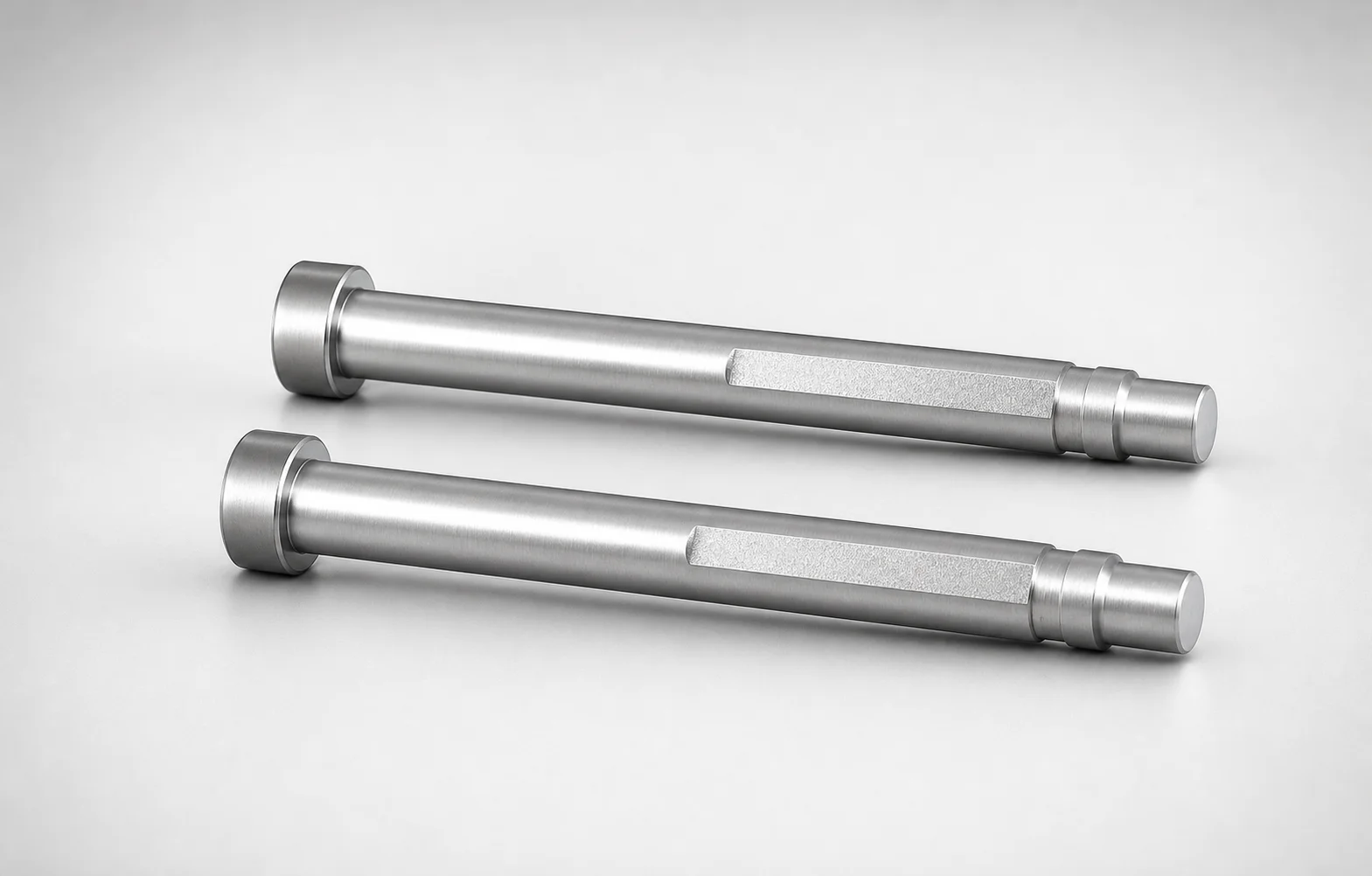
Need Custom Specifications?
Our engineering team can help with custom configurations, material selection, and volume pricing.