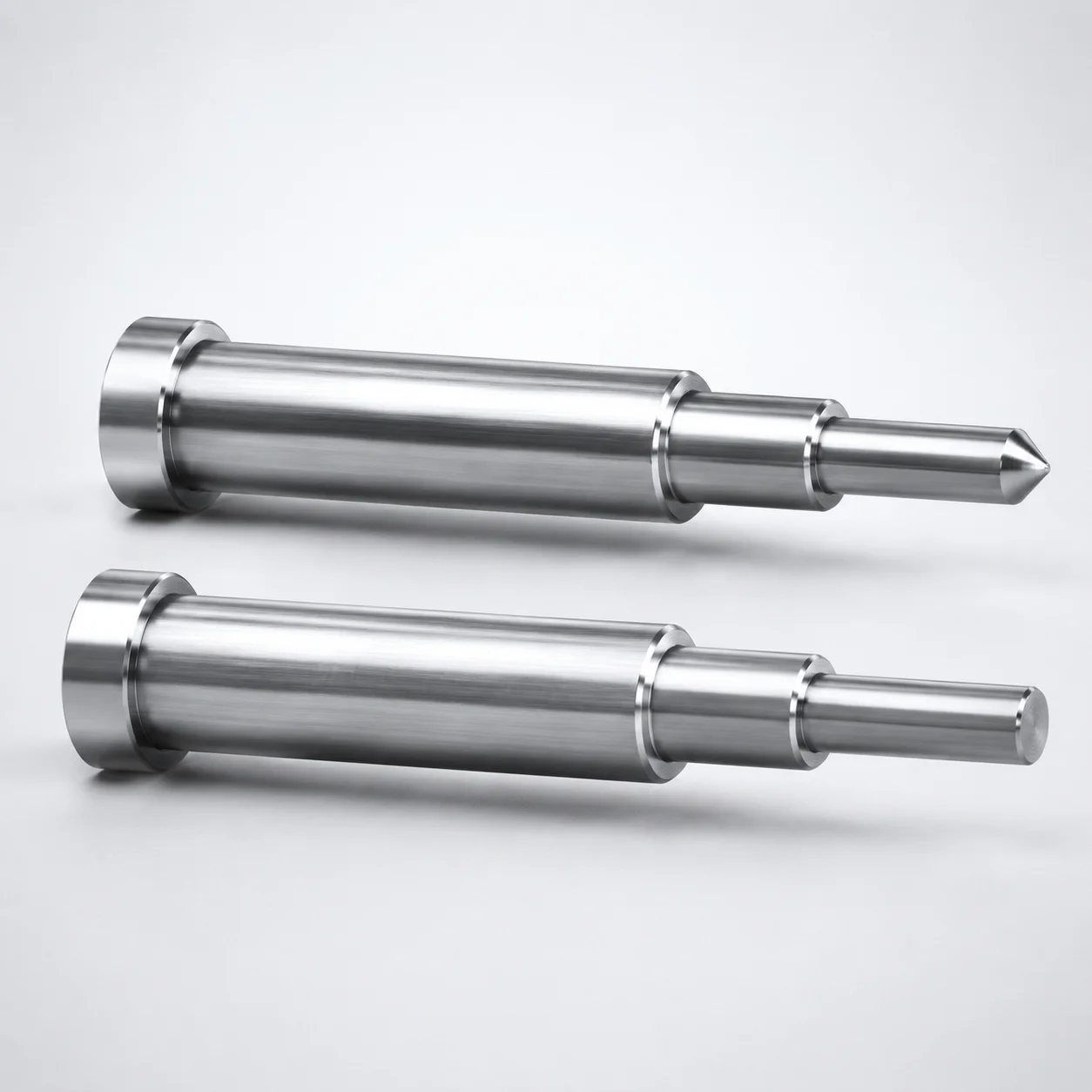
JIS Standard Steel Taperless Two-Step Core Pins Flat-Sides
Taperless two-step core pins (Steel) are precision mold components designed for reliable core positioning without taper. The two-step geometry improves locating stability during repeated mold cycles, supporting consistent assembly accuracy.
- Two-step layout for controlled positioning and repeatable core alignment
- Hardened steel for dependable wear resistance in high-cycle tooling
- Tight shaft and tip gradient tolerances help maintain accurate engagement
- Used in precision injection mold assemblies for core supports and locating
Specifications
6547 configurations available
| Material | L Dimension Tolerance | A/AAC (Tip Diameter) (mm) | D/P (Shaft Diameter) (mm) | First Step Shape | Second Step Shape | Tip Shape | No. (Nominal diameter) (mm) | C (Second step shape taper width) (mm) | F (Bearing bore length) (mm) | FC (Makes F dimension shorter than F min) (mm) | G (Tip C chamfering width) (mm) | K (Tip angle) (°) | L (L dimension) (mm) | Q (Tip R chamfering) (mm) | R (Second step type R) (mm) | S (Tip tapered width) (mm) | V (Type of the second step diameter) (mm) | W (Type of the first step) (mm) | X (First step shape taper width) (mm) | Dimension Y (mm) | type |
|---|---|---|---|---|---|---|---|---|---|---|---|---|---|---|---|---|---|---|---|---|---|
| SKH51 | 0/-0.05 | 0.5 ~ 1.47 | 1 ~ 1.49 | CB | B | B | 1.5 | - | 12 ~ 99 | - | - | - | 7 ~ 100 | - | - | - | 0.51 ~ 1.48 | - | - | 5.6 ~ 99.4 | - |
| SKH51 | 0/-0.05 | 0.5 ~ 1.47 | 1 ~ 1.49 | CB | B | B | 1.5 | - | - | 5 ~ 12.79 | - | - | 7 ~ 100 | - | - | - | 0.51 ~ 1.48 | - | - | 5.6 ~ 99.4 | - |
| SKH51 | 0/-0.05 | 0.7 ~ 1.98 | 1.5 ~ 1.99 | CB | B | B | 2 | - | 12 ~ 99 | - | - | - | 7 ~ 100 | - | - | - | 0.71 ~ 1.99 | - | - | 5.6 ~ 99.4 | - |
| SKH51 | 0/-0.05 | 0.7 ~ 1.98 | 1.5 ~ 1.99 | CB | B | B | 2 | - | - | 5 ~ 12.79 | - | - | 7 ~ 100 | - | - | - | 0.71 ~ 1.99 | - | - | 5.6 ~ 99.4 | - |
| SKH51 | 0/-0.05 | 0.7 ~ 2.48 | 2 ~ 2.49 | CB | B | B | 2.5 | - | 12 ~ 99 | - | - | - | 7 ~ 100 | - | - | - | 0.71 ~ 2.49 | - | - | 5.6 ~ 99.4 | - |
| SKH51 | 0/-0.05 | 0.7 ~ 2.48 | 2 ~ 2.49 | CB | B | B | 2.5 | - | - | 5 ~ 12.79 | - | - | 7 ~ 100 | - | - | - | 0.71 ~ 2.49 | - | - | 5.6 ~ 99.4 | - |
| SKH51 | 0/-0.05 | 1 ~ 2.98 | 2.5 ~ 2.99 | CB | B | B | 3 | - | 12 ~ 99 | - | - | - | 7 ~ 100 | - | - | - | 1.01 ~ 2.99 | - | - | 5.6 ~ 99.4 | - |
| SKH51 | 0/-0.05 | 1 ~ 2.98 | 2.5 ~ 2.99 | CB | B | B | 3 | - | - | 5 ~ 12.79 | - | - | 7 ~ 100 | - | - | - | 1.01 ~ 2.99 | - | - | 5.6 ~ 99.4 | - |
| SKH51 | 0/-0.05 | 1 ~ 3.48 | 3 ~ 3.49 | CB | B | B | 3.5 | - | 12 ~ 119 | - | - | - | 7 ~ 120 | - | - | - | 1.01 ~ 3.49 | - | - | 5.6 ~ 119.4 | - |
| SKH51 | 0/-0.05 | 1 ~ 3.48 | 3 ~ 3.49 | CB | B | B | 3.5 | - | - | 5 ~ 12.79 | - | - | 7 ~ 120 | - | - | - | 1.01 ~ 3.49 | - | - | 5.6 ~ 119.4 | - |
| SKH51 | 0/-0.05 | 1 ~ 3.98 | 3.5 ~ 3.99 | CB | B | B | 4 | - | 12 ~ 119 | - | - | - | 7 ~ 120 | - | - | - | 1.01 ~ 3.99 | - | - | 5.6 ~ 119.4 | - |
| SKH51 | 0/-0.05 | 1 ~ 3.98 | 3.5 ~ 3.99 | CB | B | B | 4 | - | - | 5 ~ 12.79 | - | - | 7 ~ 120 | - | - | - | 1.01 ~ 3.99 | - | - | 5.6 ~ 119.4 | - |
| SKH51 | 0/-0.05 | 1.5 ~ 4.48 | 4 ~ 4.49 | CB | B | B | 4.5 | - | 12 ~ 119 | - | - | - | 7 ~ 120 | - | - | - | 1.51 ~ 4.49 | - | - | 5.6 ~ 119.4 | - |
| SKH51 | 0/-0.05 | 1.5 ~ 4.48 | 4 ~ 4.49 | CB | B | B | 4.5 | - | - | 5 ~ 12.79 | - | - | 7 ~ 120 | - | - | - | 1.51 ~ 4.49 | - | - | 5.6 ~ 119.4 | - |
| SKH51 | 0/-0.05 | 1.5 ~ 4.98 | 4.5 ~ 4.99 | CB | B | B | 5 | - | 12 ~ 149 | - | - | - | 7 ~ 150 | - | - | - | 1.51 ~ 4.99 | - | - | 5.6 ~ 149.4 | - |
| SKH51 | 0/-0.05 | 1.5 ~ 4.98 | 4.5 ~ 4.99 | CB | B | B | 5 | - | - | 5 ~ 12.79 | - | - | 7 ~ 150 | - | - | - | 1.51 ~ 4.99 | - | - | 5.6 ~ 149.4 | - |
| SKH51 | 0/-0.05 | 1.5 ~ 5.48 | 5 ~ 5.49 | CB | B | B | 5.5 | - | 12 ~ 149 | - | - | - | 7 ~ 150 | - | - | - | 1.51 ~ 5.49 | - | - | 5.6 ~ 149.4 | - |
| SKH51 | 0/-0.05 | 1.5 ~ 5.48 | 5 ~ 5.49 | CB | B | B | 5.5 | - | - | 5 ~ 12.79 | - | - | 7 ~ 150 | - | - | - | 1.51 ~ 5.49 | - | - | 5.6 ~ 149.4 | - |
| SKH51 | 0/-0.05 | 2 ~ 5.98 | 5.5 ~ 5.99 | CB | B | B | 6 | - | 12 ~ 149 | - | - | - | 7 ~ 150 | - | - | - | 2.01 ~ 5.99 | - | - | 5.6 ~ 149.4 | - |
| SKH51 | 0/-0.05 | 2 ~ 5.98 | 5.5 ~ 5.99 | CB | B | B | 6 | - | - | 5 ~ 12.79 | - | - | 7 ~ 150 | - | - | - | 2.01 ~ 5.99 | - | - | 5.6 ~ 149.4 | - |
| SKH51 | 0/-0.05 | 2 ~ 6.48 | 6 ~ 6.49 | CB | B | B | 6.5 | - | 12 ~ 149 | - | - | - | 7 ~ 150 | - | - | - | 2.01 ~ 6.49 | - | - | 5.6 ~ 149.4 | - |
| SKH51 | 0/-0.05 | 2 ~ 6.48 | 6 ~ 6.49 | CB | B | B | 6.5 | - | - | 5 ~ 12.79 | - | - | 7 ~ 150 | - | - | - | 2.01 ~ 6.49 | - | - | 5.6 ~ 149.4 | - |
| SKH51 | 0/-0.05 | 2 ~ 6.98 | 6.5 ~ 6.99 | CB | B | B | 7 | - | 12 ~ 149 | - | - | - | 7 ~ 150 | - | - | - | 2.01 ~ 6.99 | - | - | 5.6 ~ 149.4 | - |
| SKH51 | 0/-0.05 | 2 ~ 6.98 | 6.5 ~ 6.99 | CB | B | B | 7 | - | - | 5 ~ 12.79 | - | - | 7 ~ 150 | - | - | - | 2.01 ~ 6.99 | - | - | 5.6 ~ 149.4 | - |
| SKH51 | 0/-0.05 | 2 ~ 7.98 | 7 ~ 7.99 | CB | B | B | 8 | - | 12 ~ 149 | - | - | - | 7 ~ 150 | - | - | - | 2.01 ~ 7.99 | - | - | 5.6 ~ 149.4 | - |
| SKH51 | 0/-0.05 | 2 ~ 7.98 | 7 ~ 7.99 | CB | B | B | 8 | - | - | 5 ~ 12.79 | - | - | 7 ~ 150 | - | - | - | 2.01 ~ 7.99 | - | - | 5.6 ~ 149.4 | - |
| SKH51 | 0/-0.05 | 2 ~ 9.98 | 8 ~ 9.99 | CB | B | B | 10 | - | 12 ~ 149 | - | - | - | 7 ~ 150 | - | - | - | 2.01 ~ 9.99 | - | - | 5.6 ~ 149.4 | - |
| SKH51 | 0/-0.05 | 2 ~ 9.98 | 8 ~ 9.99 | CB | B | B | 10 | - | - | 5 ~ 12.79 | - | - | 7 ~ 150 | - | - | - | 2.01 ~ 9.99 | - | - | 5.6 ~ 149.4 | - |
| SKH51 | 0/-0.05 | 2 ~ 12.99 | 10 ~ 12.99 | CB | B | B | 13 | - | 12 ~ 149 | - | - | - | 7 ~ 150 | - | - | - | 2.01 ~ 12.99 | - | - | 5.6 ~ 149.4 | - |
| SKH51 | 0/-0.05 | 2 ~ 12.99 | 10 ~ 12.99 | CB | B | B | 13 | - | - | 5 ~ 12.79 | - | - | 7 ~ 150 | - | - | - | 2.01 ~ 12.99 | - | - | 5.6 ~ 149.4 | - |
| SKH51 | 0/-0.05 | 2 ~ 15.99 | 13 ~ 15.99 | CB | B | B | 16 | - | 12 ~ 149 | - | - | - | 7 ~ 150 | - | - | - | 2.01 ~ 15.99 | - | - | 5.6 ~ 149.4 | - |
| SKH51 | 0/-0.05 | 2 ~ 15.99 | 13 ~ 15.99 | CB | B | B | 16 | - | - | 5 ~ 12.79 | - | - | 7 ~ 150 | - | - | - | 2.01 ~ 15.99 | - | - | 5.6 ~ 149.4 | - |
| SKH51 | 0/-0.05 | 5 ~ 19.99 | 16 ~ 19.99 | CB | B | B | 20 | - | 28 ~ 149 | - | - | - | 6.5 ~ 150 | - | - | - | 5.01 ~ 19.99 | - | - | 6.5 ~ 149.5 | - |
| SKH51 | 0/-0.05 | 5 ~ 19.99 | 16 ~ 19.99 | CB | B | B | 20 | - | - | 5 ~ 27.99 | - | - | 6.5 ~ 150 | - | - | - | 5.01 ~ 19.99 | - | - | 6.5 ~ 149.5 | - |
| SKH51 | +0.01/0 | 0.5 ~ 1.47 | 1 ~ 1.49 | CB | B | C | 1.5 | - | 12 ~ 99 | - | 0.1 ~ 0.2 | - | 7 ~ 100 | - | - | - | 0.51 ~ 1.48 | - | - | 5.6 ~ 99.4 | - |
| SKH51 | +0.01/0 | 0.5 ~ 1.47 | 1 ~ 1.49 | CB | B | C | 1.5 | - | - | 5 ~ 12.79 | 0.1 ~ 0.2 | - | 7 ~ 100 | - | - | - | 0.51 ~ 1.48 | - | - | 5.6 ~ 99.4 | - |
| SKH51 | +0.01/0 | 0.7 ~ 1.98 | 1.5 ~ 1.99 | CB | B | C | 2 | - | 12 ~ 99 | - | 0.1 ~ 0.8 | - | 7 ~ 100 | - | - | - | 0.71 ~ 1.99 | - | - | 5.6 ~ 99.4 | - |
| SKH51 | +0.01/0 | 0.7 ~ 1.98 | 1.5 ~ 1.99 | CB | B | C | 2 | - | - | 5 ~ 12.79 | 0.1 ~ 0.8 | - | 7 ~ 100 | - | - | - | 0.71 ~ 1.99 | - | - | 5.6 ~ 99.4 | - |
| SKH51 | +0.01/0 | 0.7 ~ 2.48 | 2 ~ 2.49 | CB | B | C | 2.5 | - | 12 ~ 99 | - | 0.1 ~ 1.1 | - | 7 ~ 100 | - | - | - | 0.71 ~ 2.49 | - | - | 5.6 ~ 99.4 | - |
| SKH51 | +0.01/0 | 0.7 ~ 2.48 | 2 ~ 2.49 | CB | B | C | 2.5 | - | - | 5 ~ 12.79 | 0.1 ~ 1.1 | - | 7 ~ 100 | - | - | - | 0.71 ~ 2.49 | - | - | 5.6 ~ 99.4 | - |
| SKH51 | +0.01/0 | 1 ~ 2.98 | 2.5 ~ 2.99 | CB | B | C | 3 | - | 12 ~ 99 | - | 0.1 ~ 1.3 | - | 7 ~ 100 | - | - | - | 1.01 ~ 2.99 | - | - | 5.6 ~ 99.4 | - |
| SKH51 | +0.01/0 | 1 ~ 2.98 | 2.5 ~ 2.99 | CB | B | C | 3 | - | - | 5 ~ 12.79 | 0.1 ~ 1.3 | - | 7 ~ 100 | - | - | - | 1.01 ~ 2.99 | - | - | 5.6 ~ 99.4 | - |
| SKH51 | +0.01/0 | 1 ~ 3.48 | 3 ~ 3.49 | CB | B | C | 3.5 | - | 12 ~ 119 | - | 0.1 ~ 1.6 | - | 7 ~ 120 | - | - | - | 1.01 ~ 3.49 | - | - | 5.6 ~ 119.4 | - |
| SKH51 | +0.01/0 | 1 ~ 3.48 | 3 ~ 3.49 | CB | B | C | 3.5 | - | - | 5 ~ 12.79 | 0.1 ~ 1.6 | - | 7 ~ 120 | - | - | - | 1.01 ~ 3.49 | - | - | 5.6 ~ 119.4 | - |
| SKH51 | +0.01/0 | 1 ~ 3.98 | 3.5 ~ 3.99 | CB | B | C | 4 | - | 12 ~ 119 | - | 0.1 ~ 1.8 | - | 7 ~ 120 | - | - | - | 1.01 ~ 3.99 | - | - | 5.6 ~ 119.4 | - |
| SKH51 | +0.01/0 | 1 ~ 3.98 | 3.5 ~ 3.99 | CB | B | C | 4 | - | - | 5 ~ 12.79 | 0.1 ~ 1.8 | - | 7 ~ 120 | - | - | - | 1.01 ~ 3.99 | - | - | 5.6 ~ 119.4 | - |
| SKH51 | +0.01/0 | 1.5 ~ 4.48 | 4 ~ 4.49 | CB | B | C | 4.5 | - | 12 ~ 119 | - | 0.1 ~ 2.1 | - | 7 ~ 120 | - | - | - | 1.51 ~ 4.49 | - | - | 5.6 ~ 119.4 | - |
| SKH51 | +0.01/0 | 1.5 ~ 4.48 | 4 ~ 4.49 | CB | B | C | 4.5 | - | - | 5 ~ 12.79 | 0.1 ~ 2.1 | - | 7 ~ 120 | - | - | - | 1.51 ~ 4.49 | - | - | 5.6 ~ 119.4 | - |
| SKH51 | +0.01/0 | 1.5 ~ 4.98 | 4.5 ~ 4.99 | CB | B | C | 5 | - | 12 ~ 149 | - | 0.1 ~ 2.3 | - | 7 ~ 150 | - | - | - | 1.51 ~ 4.99 | - | - | 5.6 ~ 149.4 | - |
| SKH51 | +0.01/0 | 1.5 ~ 4.98 | 4.5 ~ 4.99 | CB | B | C | 5 | - | - | 5 ~ 12.79 | 0.1 ~ 2.3 | - | 7 ~ 150 | - | - | - | 1.51 ~ 4.99 | - | - | 5.6 ~ 149.4 | - |
Product Guide
Application Scenarios+
Taperless two-step core pins are used to locate and support precision mold cores where repeatable engagement is critical. Unlike tapered designs, the two-step geometry provides a more controlled bearing/contact profile, helping maintain positional accuracy across high-cycle injection molding.
- Automotive and industrial connector housings: Suitable for locating core inserts for side-gating and internal rib features. The flat-side/two-step engagement supports stable core positioning when part eject forces and thermal cycling can shift components.
- Medical device injection molds: Applied in housings and cap components requiring tight dimensional consistency. Quenched hardened steel construction improves wear resistance at the locating interface, reducing positional drift over repeated cycles.
- Electronics and appliance overmolds: Used for core supports and alignment of fine internal cavities. The defined shaft diameter range (D/P 1–16 mm) and selectable tip/step shapes support fitting to specific cavity/core landing dimensions.
Material & Process Details+
This series is offered in SKH51 and SKD61 hardened steels, both selected for stable performance at the core-pin locating interface. SKH51 is a high-speed steel commonly associated with AISI M2-class performance, providing strong wear resistance for fine-tolerance locating surfaces. SKD61 is commonly associated with AISI H13-class hot-work steel behavior, offering good toughness for tooling subjected to thermal cycling.
- Heat treatment state: The construction is specified as quenched hardened steel, supporting a hardened surface for repeatable fits.
- Hardness/behavior trade-off: SKH51 typically emphasizes wear resistance for long life at the tip/step contact, while SKD61 tends to balance toughness to better resist chipping or cracking under loading.
- Manufacturing: Two-step profiles and flat-side features are ground/finished to maintain the provided dimensioning ranges and tolerance conditions (e.g., L tolerance sets).
Sizing & Selection Guide+
Select dimensions by matching the pin’s step geometry to the mating core/cavity pocket features. Start with the shaft diameter (D/P) in the range 1–16 mm so the bearing region controls alignment without excessive clearance. Then choose A/AAC (tip diameter) from 0.5–5 mm to match the intended locating/entry size in the core block.
- Length (L): Use L = 6.5–30 mm and apply the specified L tolerance options (0/-0.05 or +0.01/0), depending on whether you need tighter control toward engagement depth.
- Step shapes: Confirm the first step shape (CB/CC/CD/CE) and second step shape (B/C/D/E) along with tip shape (B/C/G/R/S/T) to ensure the contact profile matches the pocket.
- Fit considerations: Use the provided tolerance direction on L and the nominal diameter range (1.5–20 mm) to prevent under-engagement (too short) or interference (too long). Where dimensions are fixed (e.g., X = 0.1–1 mm), verify mating geometry accordingly.
Frequently Asked Questions
Which material should I choose for a core pin that experiences high wear at the two-step locating surface—SKH51 or SKD61?+
How do the L dimension tolerance options affect core positioning reliability?+
What dimensional set should I verify first when matching the core pin to the mold core pocket—D/P or A/AAC?+
Can I select different step and tip shapes for the same nominal diameter, and why does it matter?+
How do I choose L vs. F-related adjustments to avoid under-engagement?+
Related Products
Need Custom Specifications?
Our engineering team can help with custom configurations, material selection, and volume pricing.