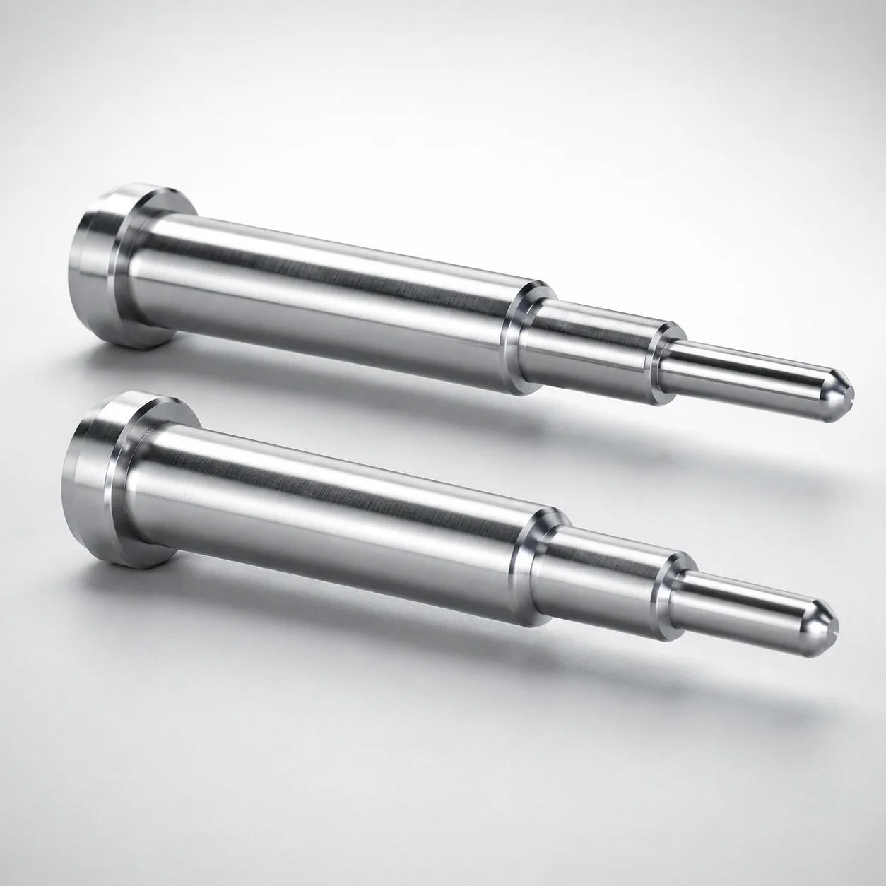
JIS Standard Steel Precision Taperless Two-Step Core Pins Flat-Sided
Precision taperless two-step core pins (hardened steel) provide reliable two-step positioning for mold cores. The flat-sided head helps prevent rotation and supports consistent ejection accuracy during production.
- Two-step taperless geometry aligns cores with stable seating
- Built from hardened steel for abrasion resistance and service life
- Supports tight shaft fit with referenced +0.01/0 to 0/-0.05 tolerances
- Used in injection molding for core pin locating and support
Specifications
6918 configurations available
| Material | L Dimension Tolerance | A/AAC (Tip Diameter) (mm) | D/P (Shaft Diameter) (mm) | First Step Shape | Second Step Shape | Tip Shape | C (Second step shape taper width) (mm) | F (Bearing bore length) (mm) | FC (Makes F dimension shorter than F min) (mm) | G (Tip C chamfering width) (mm) | K (Tip angle) (°) | L (L dimension) (mm) | Q (Tip R chamfering) (mm) | R (Second step type R) (mm) | S (Tip tapered width) (mm) | V (Type of the second step diameter) (mm) | W (Type of the first step) (mm) | X (First step shape taper width) (mm) | Dimension Y (mm) | type |
|---|---|---|---|---|---|---|---|---|---|---|---|---|---|---|---|---|---|---|---|---|
| SKH51 | 0/-0.05 | 0.5 ~ 0.98 | 1 | CB | B | B | - | 12 ~ 99.5 | - | - | - | 7 ~ 100 | - | - | - | 0.51 ~ 0.99 | - | - | 5.6 ~ 99.4 | - |
| SKH51 | 0/-0.05 | 0.5 ~ 0.98 | 1 | CB | B | B | - | - | 5 ~ 12.79 | - | - | 7 ~ 100 | - | - | - | 0.51 ~ 0.99 | - | - | 5.6 ~ 99.4 | - |
| SKH51 | 0/-0.05 | 0.5 ~ 1.48 | 1.5 | CB | B | B | - | 12 ~ 99 | - | - | - | 7 ~ 100 | - | - | - | 0.51 ~ 1.49 | - | - | 5.6 ~ 99.4 | - |
| SKH51 | 0/-0.05 | 0.5 ~ 1.48 | 1.5 | CB | B | B | - | - | 5 ~ 12.79 | - | - | 7 ~ 100 | - | - | - | 0.51 ~ 1.49 | - | - | 5.6 ~ 99.4 | - |
| SKH51 | 0/-0.05 | 0.7 ~ 1.98 | 2 | CB | B | B | - | 12 ~ 99 | - | - | - | 7 ~ 100 | - | - | - | 0.71 ~ 1.99 | - | - | 5.6 ~ 99.4 | - |
| SKH51 | 0/-0.05 | 0.7 ~ 1.98 | 2 | CB | B | B | - | - | 5 ~ 12.79 | - | - | 7 ~ 100 | - | - | - | 0.71 ~ 1.99 | - | - | 5.6 ~ 99.4 | - |
| SKH51 | 0/-0.05 | 0.7 ~ 2.48 | 2.5 | CB | B | B | - | 12 ~ 99 | - | - | - | 7 ~ 100 | - | - | - | 0.71 ~ 2.49 | - | - | 5.6 ~ 99.4 | - |
| SKH51 | 0/-0.05 | 0.7 ~ 2.48 | 2.5 | CB | B | B | - | - | 5 ~ 12.79 | - | - | 7 ~ 100 | - | - | - | 0.71 ~ 2.49 | - | - | 5.6 ~ 99.4 | - |
| SKH51 | 0/-0.05 | 1 ~ 2.98 | 3 | CB | B | B | - | 12 ~ 99 | - | - | - | 7 ~ 100 | - | - | - | 1.01 ~ 2.99 | - | - | 5.6 ~ 99.4 | - |
| SKH51 | 0/-0.05 | 1 ~ 2.98 | 3 | CB | B | B | - | - | 5 ~ 12.79 | - | - | 7 ~ 100 | - | - | - | 1.01 ~ 2.99 | - | - | 5.6 ~ 99.4 | - |
| SKH51 | 0/-0.05 | 1 ~ 3.48 | 3.5 | CB | B | B | - | 12 ~ 119.5 | - | - | - | 7 ~ 120 | - | - | - | 1.01 ~ 3.49 | - | - | 5.6 ~ 119.5 | - |
| SKH51 | 0/-0.05 | 1 ~ 3.48 | 3.5 | CB | B | B | - | - | 5 ~ 12.79 | - | - | 7 ~ 120 | - | - | - | 1.01 ~ 3.49 | - | - | 5.6 ~ 119.5 | - |
| SKH51 | 0/-0.05 | 1 ~ 3.89 | 4 | CB | B | B | - | 12 ~ 119.5 | - | - | - | 7 ~ 120 | - | - | - | 1.01 ~ 3.99 | - | - | 5.6 ~ 119.5 | - |
| SKH51 | 0/-0.05 | 1 ~ 3.89 | 4 | CB | B | B | - | - | 5 ~ 12.79 | - | - | 7 ~ 120 | - | - | - | 1.01 ~ 3.99 | - | - | 5.6 ~ 119.5 | - |
| SKH51 | 0/-0.05 | 1.5 ~ 4.48 | 4.5 | CB | B | B | - | 12 ~ 119.5 | - | - | - | 7 ~ 120 | - | - | - | 1.51 ~ 4.49 | - | - | 5.6 ~ 119.5 | - |
| SKH51 | 0/-0.05 | 1.5 ~ 4.48 | 4.5 | CB | B | B | - | - | 5 ~ 12.79 | - | - | 7 ~ 120 | - | - | - | 1.51 ~ 4.49 | - | - | 5.6 ~ 119.5 | - |
| SKH51 | 0/-0.05 | 1.5 ~ 4.98 | 5 | CB | B | B | - | 12 ~ 149.5 | - | - | - | 7 ~ 150 | - | - | - | 1.51 ~ 4.99 | - | - | 5.6 ~ 149.4 | - |
| SKH51 | 0/-0.05 | 1.5 ~ 4.98 | 5 | CB | B | B | - | - | 5 ~ 12.79 | - | - | 7 ~ 150 | - | - | - | 1.51 ~ 4.99 | - | - | 5.6 ~ 149.4 | - |
| SKH51 | 0/-0.05 | 1.5 ~ 5.48 | 5.5 | CB | B | B | - | 12 ~ 149.5 | - | - | - | 7 ~ 150 | - | - | - | 1.51 ~ 5.49 | - | - | 5.6 ~ 149.4 | - |
| SKH51 | 0/-0.05 | 1.5 ~ 5.48 | 5.5 | CB | B | B | - | - | 5 ~ 12.79 | - | - | 7 ~ 150 | - | - | - | 1.51 ~ 5.49 | - | - | 5.6 ~ 149.4 | - |
| SKH51 | 0/-0.05 | 2 ~ 5.98 | 6 | CB | B | B | - | 12 ~ 149.5 | - | - | - | 7 ~ 150 | - | - | - | 2.01 ~ 5.99 | - | - | 5.6 ~ 149.4 | - |
| SKH51 | 0/-0.05 | 2 ~ 5.98 | 6 | CB | B | B | - | - | 5 ~ 12.79 | - | - | 7 ~ 150 | - | - | - | 2.01 ~ 5.99 | - | - | 5.6 ~ 149.4 | - |
| SKH51 | 0/-0.05 | 2 ~ 6.48 | 6.5 | CB | B | B | - | 12 ~ 149.5 | - | - | - | 7 ~ 150 | - | - | - | 2.01 ~ 6.49 | - | - | 5.6 ~ 149.4 | - |
| SKH51 | 0/-0.05 | 2 ~ 6.48 | 6.5 | CB | B | B | - | - | 5 ~ 12.79 | - | - | 7 ~ 150 | - | - | - | 2.01 ~ 6.49 | - | - | 5.6 ~ 149.4 | - |
| SKH51 | 0/-0.05 | 2 ~ 6.98 | 7 | CB | B | B | - | 12 ~ 149.5 | - | - | - | 7 ~ 150 | - | - | - | 2.01 ~ 6.99 | - | - | 5.6 ~ 149.4 | - |
| SKH51 | 0/-0.05 | 2 ~ 6.98 | 7 | CB | B | B | - | - | 5 ~ 12.79 | - | - | 7 ~ 150 | - | - | - | 2.01 ~ 6.99 | - | - | 5.6 ~ 149.4 | - |
| SKH51 | 0/-0.05 | 2 ~ 7.98 | 8 | CB | B | B | - | 12 ~ 149.5 | - | - | - | 7 ~ 150 | - | - | - | 2.01 ~ 7.99 | - | - | 5.6 ~ 149.4 | - |
| SKH51 | 0/-0.05 | 2 ~ 7.98 | 8 | CB | B | B | - | - | 5 ~ 12.79 | - | - | 7 ~ 150 | - | - | - | 2.01 ~ 7.99 | - | - | 5.6 ~ 149.4 | - |
| SKH51 | 0/-0.05 | 2 ~ 9.98 | 10 | CB | B | B | - | 12 ~ 149.5 | - | - | - | 7 ~ 150 | - | - | - | 2.01 ~ 9.99 | - | - | 5.6 ~ 149.4 | - |
| SKH51 | 0/-0.05 | 2 ~ 9.98 | 10 | CB | B | B | - | - | 5 ~ 12.79 | - | - | 7 ~ 150 | - | - | - | 2.01 ~ 9.99 | - | - | 5.6 ~ 149.4 | - |
| SKH51 | 0/-0.05 | 2 ~ 12.99 | 13 | CB | B | B | - | 12 ~ 149 | - | - | - | 7 ~ 150 | - | - | - | 2.01 ~ 12.99 | - | - | 5.6 ~ 149.4 | - |
| SKH51 | 0/-0.05 | 2 ~ 12.99 | 13 | CB | B | B | - | - | 5 ~ 12.79 | - | - | 7 ~ 150 | - | - | - | 2.01 ~ 12.99 | - | - | 5.6 ~ 149.4 | - |
| SKH51 | 0/-0.05 | 2 ~ 15.99 | 16 | CB | B | B | - | 12 ~ 149 | - | - | - | 7 ~ 150 | - | - | - | 2.01 ~ 15.99 | - | - | 5.6 ~ 149.4 | - |
| SKH51 | 0/-0.05 | 2 ~ 15.99 | 16 | CB | B | B | - | - | 5 ~ 12.79 | - | - | 7 ~ 150 | - | - | - | 2.01 ~ 15.99 | - | - | 5.6 ~ 149.4 | - |
| SKH51 | 0/-0.05 | 5 ~ 19.99 | 20 | CB | B | B | - | 28 ~ 149 | - | - | - | 6.5 ~ 150 | - | - | - | 5.01 ~ 19.99 | - | - | 6.5 ~ 149.5 | - |
| SKH51 | 0/-0.05 | 5 ~ 19.99 | 20 | CB | B | B | - | - | 5 ~ 27.99 | - | - | 6.5 ~ 150 | - | - | - | 5.01 ~ 19.99 | - | - | 6.5 ~ 149.5 | - |
| SKH51 | +0.01/0 | 0.5 ~ 1.48 | 1 | CB | B | C | - | 12 ~ 99.5 | - | 0.1 ~ 0.6 | - | 7 ~ 100 | - | - | - | 0.51 ~ 1.49 | - | - | 5.6 ~ 99.4 | - |
| SKH51 | +0.01/0 | 0.5 ~ 1.48 | 1 | CB | B | C | - | - | 5 ~ 12.79 | 0.1 ~ 0.6 | - | 7 ~ 100 | - | - | - | 0.51 ~ 1.49 | - | - | 5.6 ~ 99.4 | - |
| SKH51 | +0.01/0 | 0.5 ~ 1.48 | 1.5 | CB | B | C | - | 12 ~ 99.5 | - | 0.1 ~ 0.6 | - | 7 ~ 120 | - | - | - | 0.51 ~ 1.49 | - | - | 5.6 ~ 99.4 | - |
| SKH51 | +0.01/0 | 0.5 ~ 1.48 | 1.5 | CB | B | C | - | - | 5 ~ 12.79 | 0.1 ~ 0.6 | - | 7 ~ 120 | - | - | - | 0.51 ~ 1.49 | - | - | 5.6 ~ 99.4 | - |
| SKH51 | +0.01/0 | 0.7 ~ 1.98 | 2 | CB | B | C | - | 12 ~ 99.5 | - | 0.1 ~ 0.8 | - | 7 ~ 120 | - | - | - | 0.71 ~ 1.99 | - | - | 5.6 ~ 99.4 | - |
| SKH51 | +0.01/0 | 0.7 ~ 1.98 | 2 | CB | B | C | - | - | 5 ~ 12.79 | 0.1 ~ 0.8 | - | 7 ~ 120 | - | - | - | 0.71 ~ 1.99 | - | - | 5.6 ~ 99.4 | - |
| SKH51 | +0.01/0 | 0.75 ~ 2.49 | 2.5 | CB | B | C | - | 12 ~ 99.5 | - | 0.1 ~ 1.1 | - | 7 ~ 120 | - | - | - | 0.71 ~ 2.49 | - | - | 5.6 ~ 99.4 | - |
| SKH51 | +0.01/0 | 0.75 ~ 2.49 | 2.5 | CB | B | C | - | - | 5 ~ 12.79 | 0.1 ~ 1.1 | - | 7 ~ 120 | - | - | - | 0.71 ~ 2.49 | - | - | 5.6 ~ 99.4 | - |
| SKH51 | +0.01/0 | 1 ~ 2.98 | 3 | CB | B | C | - | 12 ~ 99.5 | - | 0.1 ~ 1.3 | - | 7 ~ 120 | - | - | - | 1.01 ~ 2.99 | - | - | 5.6 ~ 99.4 | - |
| SKH51 | +0.01/0 | 1 ~ 2.98 | 3 | CB | B | C | - | - | 5 ~ 12.79 | 0.1 ~ 1.3 | - | 7 ~ 120 | - | - | - | 1.01 ~ 2.99 | - | - | 5.6 ~ 99.4 | - |
| SKH51 | +0.01/0 | 1 ~ 3.48 | 3.5 | CB | B | C | - | 12 ~ 99.5 | - | 0.1 ~ 1.6 | - | 7 ~ 120 | - | - | - | 1.01 ~ 3.49 | - | - | 5.6 ~ 99.4 | - |
| SKH51 | +0.01/0 | 1 ~ 3.48 | 3.5 | CB | B | C | - | - | 5 ~ 12.79 | 0.1 ~ 1.6 | - | 7 ~ 120 | - | - | - | 1.01 ~ 3.49 | - | - | 5.6 ~ 99.4 | - |
| SKH51 | +0.01/0 | 1 ~ 3.89 | 4 | CB | B | C | - | 12 ~ 119.5 | - | 0.1 ~ 1.8 | - | 7 ~ 120 | - | - | - | 1.01 ~ 3.99 | - | - | 5.6 ~ 119.8 | - |
| SKH51 | +0.01/0 | 1 ~ 3.89 | 4 | CB | B | C | - | - | 5 ~ 12.79 | 0.1 ~ 1.8 | - | 7 ~ 120 | - | - | - | 1.01 ~ 3.99 | - | - | 5.6 ~ 119.8 | - |
Product Guide
Application Scenarios+
This hardened, flat-sided two-step core pin is used in injection mold tooling where repeatable core locating and resistance to rotation are critical. The two-step taperless seating supports stable positioning of the core over repeated cycles, helping maintain consistent core-to-cavity alignment.
- Automotive connector and housing molds: Flat-sided geometry helps prevent core rotation during ejection, supporting stable ejection accuracy when cores experience intermittent side loads.
- Medical device housings and caps: The taperless two-step layout improves core support at the seating surfaces, which is beneficial when tight dimensional repeatability is required across high-volume production.
- General electronics housings: Hardened steel and the specified shaft fit tolerances support long service life under abrasion from repeated alignment and runner/core movement.
With flat-sided contact, the pin variant is especially suited for applications where rotation control and consistent seating are needed to protect cavity formation and downstream part tolerances.
Material & Process Details+
These taperless two-step core pins are available in SKH51 or SKD61 hardened steel options, both intended for wear resistance in core locating service.
- SKH51: Typically selected for abrasion resistance where higher hardness is beneficial. Expect a trade-off of reduced toughness versus tougher tool steels if heavily shock-loaded.
- SKD61: Commonly chosen for balanced hot-work tool performance, supporting better toughness for molds that experience thermal cycling and intermittent mechanical stress.
In manufacturing, pins are precision machined to the required taperless two-step geometry, then supplied in a hardened condition suitable for stable wear behavior. Final inspection focuses on the shaft diameter and seating features to maintain the specified fit tolerance range of +0.01/0 to 0/-0.05 (by length/dimension as provided in the spec).
Choose SKD61 when toughness and thermal cycling durability are priorities, or SKH51 when wear resistance at the locating surfaces is the dominant requirement.
Sizing & Selection Guide+
Start by matching the pin’s shaft diameter D/P to the mold’s core guide bore. This product supports D/P = 1 to 20 mm, so select the closest nominal diameter and verify that the pin can achieve the intended fit using the provided tolerance window (referenced as +0.01/0 to 0/-0.05).
- Match the seating length L: The available L = 2.2 to 100.01 mm must cover the required engagement and support depth at the two-step locating surfaces.
- Select step geometry: Choose the first step shape (CB/CC/CD/CE) and second step shape (B/C/D/E) that correspond to your core locating profile. Fixed taper widths include X = 0.1 to 1 mm and C = 0.1 to 1 mm.
- Confirm bearing bore length F: Use F = 12 to 28 mm and the FC option ranges (e.g., 5 to 12.79, 5 to 27.99, 5 to 11.99 mm) to ensure the effective length does not undercut your design minimums.
Because step/tip features (tip diameter A 0.5–5 mm, chamfer widths, and tip angle K) vary, verify the bearing contact area and clearance against the core bore before final assembly.
Frequently Asked Questions
Which material should I choose for core pin locating—SKH51 or SKD61—when wear versus toughness is my main concern?+
How do I select the correct pin diameter and tolerance window to ensure stable core fit in a taperless two-step design?+
What do the two-step taperless features control, and how does the flat-sided head affect ejection alignment?+
How do I choose the step and tip shapes (CB/CC/CD/CE, B/C/D/E, tip shapes) so the locating profile matches my core?+
Which length-related parameters should I verify—L, F, and FC—to avoid under-engagement in the bearing bore?+
Related Products
Need Custom Specifications?
Our engineering team can help with custom configurations, material selection, and volume pricing.