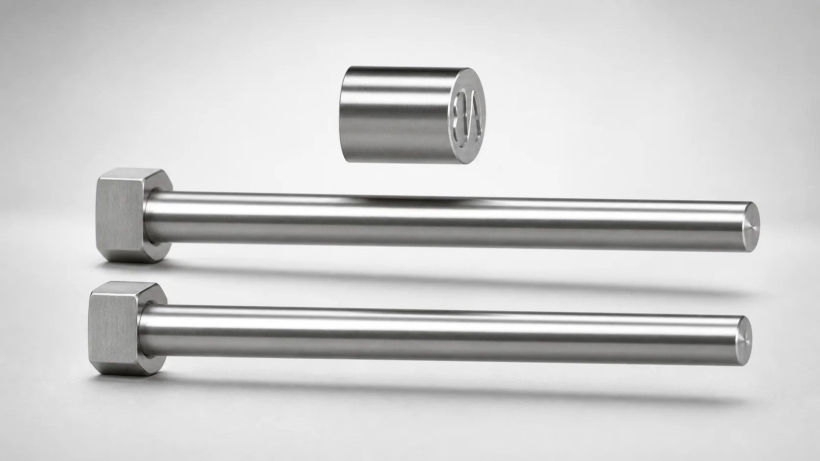
SKH51 Steel With Engraving Straight Core Pins
With engraving straight core pins (SKH51 steel) are engineered for mold core positioning with integrated convex character marking to support clear sequential identification. The designation-by-WOS engraving helps streamline inspection and assembly in production.
- Convex character with engraving for readable sequential identification
- Quenched hardening steel construction for wear-resistant core performance
- Supports tight L dimension tolerance (+0.05/0) for reliable fit and alignment
- Built for die and mold applications requiring marked core components
Specifications
60 configurations available
| Shaft Diameter Tolerance | D/P (Shaft Diameter) (mm) | Number of Outer Ring Characters | No. (Nominal diameter) (mm) | L (L dimension) (mm) | Engraving character designation | type |
|---|---|---|---|---|---|---|
| 0/-0.005 | 1 | 1 characters | - | 10 ~ 100 | ※Designation by WOS | - |
| 0/-0.005 | 1.1 | 1 characters | - | 10 ~ 100 | ※Designation by WOS | - |
| 0/-0.005 | 1.2 | 1 characters | - | 10 ~ 100 | ※Designation by WOS | - |
| 0/-0.005 | 1.3 | 1 characters | - | 10 ~ 100 | ※Designation by WOS | - |
| 0/-0.005 | 1.4 | 1 characters | - | 10 ~ 100 | ※Designation by WOS | - |
| 0/-0.005 | 1.5 | 1 characters | - | 10 ~ 100 | ※Designation by WOS | - |
| 0/-0.005 | 1.6 | 1 characters | - | 10 ~ 100 | ※Designation by WOS | - |
| 0/-0.005 | 1.7 | 1 characters | - | 10 ~ 100 | ※Designation by WOS | - |
| 0/-0.005 | 1.8 | 1 characters | - | 10 ~ 100 | ※Designation by WOS | - |
| 0/-0.005 | 1.9 | 1 characters | - | 10 ~ 100 | ※Designation by WOS | - |
| 0/-0.005 | 2 | 1 characters | - | 10 ~ 100 | ※Designation by WOS | - |
| 0/-0.005 | 2.5 | 1 characters | - | 10 ~ 100 | ※Designation by WOS | - |
| 0/-0.005 | 3 | 1 characters | - | 10 ~ 100 | ※Designation by WOS | - |
| 0/-0.005 | 3.5 | 1 characters | - | 10 ~ 120 | ※Designation by WOS | - |
| 0/-0.005 | 4 | 1 characters | - | 10 ~ 120 | ※Designation by WOS | - |
| 0/-0.005 | 2 | 2 characters | - | 10 ~ 100 | ※Designation by WOS | - |
| 0/-0.005 | 2.5 | 2 characters | - | 10 ~ 100 | ※Designation by WOS | - |
| 0/-0.005 | 3 | 2 characters | - | 10 ~ 100 | ※Designation by WOS | - |
| 0/-0.005 | 3.5 | 2 characters | - | 10 ~ 120 | ※Designation by WOS | - |
| 0/-0.005 | 4 | 2 characters | - | 10 ~ 120 | ※Designation by WOS | - |
| 0/-0.005 | 1 ~ 1.49 | 1 characters | 1.5 | 10 ~ 100 | ※Designation by WOS | - |
| 0/-0.005 | 1.5 ~ 1.99 | 1 characters | 2 | 10 ~ 100 | ※Designation by WOS | - |
| 0/-0.005 | 2 ~ 2.49 | 1 characters | 2.5 | 10 ~ 100 | ※Designation by WOS | - |
| 0/-0.005 | 2.5 ~ 2.99 | 1 characters | 3 | 10 ~ 100 | ※Designation by WOS | - |
| 0/-0.005 | 3 ~ 3.49 | 1 characters | 3.5 | 10 ~ 120 | ※Designation by WOS | - |
| 0/-0.005 | 3.5 ~ 3.99 | 1 characters | 4 | 10 ~ 120 | ※Designation by WOS | - |
| 0/-0.005 | 2 ~ 2.49 | 2 characters | 2.5 | 10 ~ 100 | ※Designation by WOS | - |
| 0/-0.005 | 2.5 ~ 2.99 | 2 characters | 3 | 10 ~ 100 | ※Designation by WOS | - |
| 0/-0.005 | 3 ~ 3.49 | 2 characters | 3.5 | 10 ~ 120 | ※Designation by WOS | - |
| 0/-0.005 | 3.5 ~ 3.99 | 2 characters | 4 | 10 ~ 120 | ※Designation by WOS | - |
| -0.01/-0.02 | 1 | 1 characters | - | 10 ~ 100 | ※Designation by WOS | - |
| -0.01/-0.02 | 1.1 | 1 characters | - | 10 ~ 100 | ※Designation by WOS | - |
| -0.01/-0.02 | 1.2 | 1 characters | - | 10 ~ 100 | ※Designation by WOS | - |
| -0.01/-0.02 | 1.3 | 1 characters | - | 10 ~ 100 | ※Designation by WOS | - |
| -0.01/-0.02 | 1.4 | 1 characters | - | 10 ~ 100 | ※Designation by WOS | - |
| -0.01/-0.02 | 1.5 | 1 characters | - | 10 ~ 100 | ※Designation by WOS | - |
| -0.01/-0.02 | 1.6 | 1 characters | - | 10 ~ 100 | ※Designation by WOS | - |
| -0.01/-0.02 | 1.7 | 1 characters | - | 10 ~ 100 | ※Designation by WOS | - |
| -0.01/-0.02 | 1.8 | 1 characters | - | 10 ~ 100 | ※Designation by WOS | - |
| -0.01/-0.02 | 1.9 | 1 characters | - | 10 ~ 100 | ※Designation by WOS | - |
| -0.01/-0.02 | 2 | 1 characters | - | 10 ~ 100 | ※Designation by WOS | - |
| -0.01/-0.02 | 2.5 | 1 characters | - | 10 ~ 100 | ※Designation by WOS | - |
| -0.01/-0.02 | 3 | 1 characters | - | 10 ~ 100 | ※Designation by WOS | - |
| -0.01/-0.02 | 3.5 | 1 characters | - | 10 ~ 120 | ※Designation by WOS | - |
| -0.01/-0.02 | 4 | 1 characters | - | 10 ~ 120 | ※Designation by WOS | - |
| -0.01/-0.02 | 2 | 2 characters | - | 10 ~ 100 | ※Designation by WOS | - |
| -0.01/-0.02 | 2.5 | 2 characters | - | 10 ~ 100 | ※Designation by WOS | - |
| -0.01/-0.02 | 3 | 2 characters | - | 10 ~ 100 | ※Designation by WOS | - |
| -0.01/-0.02 | 3.5 | 2 characters | - | 10 ~ 120 | ※Designation by WOS | - |
| -0.01/-0.02 | 4 | 2 characters | - | 10 ~ 120 | ※Designation by WOS | - |
Product Guide
Application Scenarios+
Core pins with engraved identification are used in injection mold tooling where repeatable core positioning and fast, error-resistant assembly are critical. The convex character WOS engraving supports clear sequential identification during mold build-up, teardown, and in-process inspection—especially when multiple cavities or cores are mounted close together.
- Automotive connector and housing molds: helps technicians match the correct core pin to each cavity insert, reducing misalignment risk and supporting consistent dimensional performance during high-volume production.
- Medical device housings: the marked core components improve traceability during QA and rework, aiding controlled assembly workflows where accurate core location is essential.
- Consumer electronics enclosures: sequential identification streamlines automated and manual inspection of core modules, supporting reliable fit and alignment when pins are replaced or serviced.
This variant’s SKH51 quenched hardening steel and the specified L dimension tolerance (+0.05/0) make it suited for maintaining stable alignment under repeated mold operations.
Material & Process Details+
The pin is made from SKH51 steel (high-speed steel type), selected for its ability to retain hardness and resist wear at the temperatures encountered in mold core tooling. The meta description specifies quenched hardening steel construction, indicating a heat-treated condition designed for durability in sliding/locating contact areas.
- Wear resistance: enhanced by the quenched hardened microstructure, supporting longer service life in core positioning applications.
- Toughness trade-off: as hardness increases after quenching and tempering, impact toughness can reduce versus lower-hardness mold steels—important when pins experience shock during assembly.
- Manufacturing process: steel is machined to the nominal core pin dimensions, then heat treated to the hardened state appropriate for SKH51 performance, followed by engraving of the ※Designation by WOS marking.
If alternative mold steels were used, softer grades may improve shock resistance but typically reduce wear life; hardened SKH51 favors high-cycle, wear-driven environments.
Sizing & Selection Guide+
Selection is based on matching the nominal diameter and the shaft diameter range to the mating core support features. This product provides D/P (Shaft Diameter) of 1 ~ 4 mm with nominal sizes 1.5, 2, 2.5, 3, 3.5, 4 mm.
- Choose the nominal diameter: pick the listed No. (nominal diameter) that matches the pin bore/guide fit requirement.
- Account for shaft diameter tolerance: the shaft diameter tolerance is 0/-0.005 or -0.01/-0.02, so plan clearances accordingly to achieve consistent locating without binding.
- Match the length (L): available L ranges are 10 ~ 100 mm or 10 ~ 120 mm. Ensure the pin engagement length supports core alignment across the full opening/closing travel.
For axial fit, follow the specified L dimension tolerance (+0.05/0) to maintain stack-up consistency between locating elements. Character engraving format is fixed to ※Designation by WOS, while ring character count is configurable by model as 1 or 2 characters.
Frequently Asked Questions
What steel and heat-treated condition should I expect for these straight core pins?+
The pin material is SKH51 steel with quenched hardening steel construction, indicating a hardened heat-treated state suitable for wear resistance in core locating applications.
How does the WOS engraving affect sequential core identification during mold assembly?+
The engraving is specified as ※Designation by WOS, using a convex character style. This marking enables clear sequential identification for correct pin-to-core assignment during build, inspection, and rework.
What shaft diameter ranges and tolerances are available for correct fit with the mold core supports?+
The available D/P (shaft diameter) range is 1 ~ 4 mm with nominal diameters 1.5, 2, 2.5, 3, 3.5, 4.
Shaft diameter tolerances are listed as 0/-0.005 or -0.01/-0.02, so you should design the mating bore/guide clearance to accommodate the lower limit.
How should I select the L (length) to ensure reliable core alignment?+
The available L ranges are 10 ~ 100 mm and 10 ~ 120 mm. Use the required engagement length for alignment and consider the L dimension tolerance (+0.05/0) when calculating dimensional stack-up across core components.
Is the engraving character count selectable, and does it impact compatibility?+
The model supports number of outer ring characters as 1 or 2 characters. The engraving designation method remains fixed to ※Designation by WOS; compatibility is primarily governed by the pin’s geometric specs (diameter and L tolerances), not the character count.
Related Products
Need Custom Specifications?
Our engineering team can help with custom configurations, material selection, and volume pricing.