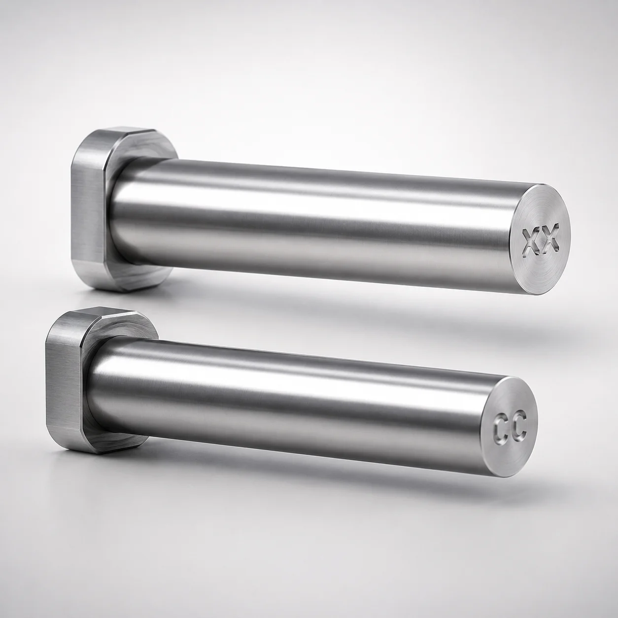
Designation by WOS Straight Core Pins with Engraving Concave Character
Designation by WOS straight core pins (SKH51 steel) with concave character engraving support accurate core positioning and clear mold identification. The engraving design helps organize cavity features while maintaining reliable ejection alignment.
- With engraving using concave character for durable part identification
- SKH51 hardening steel construction supports wear-resistant core pin performance
- Matched L dimension tolerance (+0.02/0) for stable assembly in core sets
- Built for standard mold core functions in tooling that require engraved designation
Specifications
328 configurations available
| Shaft Diameter Tolerance | D/P (Shaft Diameter) (mm) | Number of Outer Ring Characters | No. (Nominal diameter) (mm) | L (L dimension) (mm) | Engraving character designation | type |
|---|---|---|---|---|---|---|
| 0/-0.005 | 0.6 | 1 characters | - | 10 ~ 100 | ※Designation by WOS | - |
| 0/-0.005 | 0.7 | 1 characters | - | 10 ~ 100 | ※Designation by WOS | - |
| 0/-0.005 | 0.8 | 1 characters | - | 10 ~ 100 | ※Designation by WOS | - |
| 0/-0.005 | 0.9 | 1 characters | - | 10 ~ 100 | ※Designation by WOS | - |
| 0/-0.005 | 1 | 1 characters | - | 10 ~ 100 | ※Designation by WOS | - |
| 0/-0.005 | 1.1 | 1 characters | - | 10 ~ 100 | ※Designation by WOS | - |
| 0/-0.005 | 1.2 | 1 characters | - | 10 ~ 100 | ※Designation by WOS | - |
| 0/-0.005 | 1.3 | 1 characters | - | 10 ~ 100 | ※Designation by WOS | - |
| 0/-0.005 | 1.4 | 1 characters | - | 10 ~ 100 | ※Designation by WOS | - |
| 0/-0.005 | 1.5 | 1 characters | - | 10 ~ 100 | ※Designation by WOS | - |
| 0/-0.005 | 1.6 | 1 characters | - | 10 ~ 100 | ※Designation by WOS | - |
| 0/-0.005 | 1.7 | 1 characters | - | 10 ~ 100 | ※Designation by WOS | - |
| 0/-0.005 | 1.8 | 1 characters | - | 10 ~ 100 | ※Designation by WOS | - |
| 0/-0.005 | 1.9 | 1 characters | - | 10 ~ 100 | ※Designation by WOS | - |
| 0/-0.005 | 2 | 1 characters | - | 10 ~ 100 | ※Designation by WOS | - |
| 0/-0.005 | 2.5 | 1 characters | - | 10 ~ 100 | ※Designation by WOS | - |
| 0/-0.005 | 3 | 1 characters | - | 10 ~ 100 | ※Designation by WOS | - |
| 0/-0.005 | 3.5 | 1 characters | - | 10 ~ 120 | ※Designation by WOS | - |
| 0/-0.005 | 4 | 1 characters | - | 10 ~ 120 | ※Designation by WOS | - |
| 0/-0.005 | 4.5 | 1 characters | - | 10 ~ 120 | ※Designation by WOS | - |
| 0/-0.005 | 5 | 1 characters | - | 10 ~ 150 | ※Designation by WOS | - |
| 0/-0.005 | 5.5 | 1 characters | - | 10 ~ 150 | ※Designation by WOS | - |
| 0/-0.005 | 6 | 1 characters | - | 10 ~ 150 | ※Designation by WOS | - |
| 0/-0.005 | 6.5 | 1 characters | - | 10 ~ 150 | ※Designation by WOS | - |
| 0/-0.005 | 7 | 1 characters | - | 10 ~ 150 | ※Designation by WOS | - |
| 0/-0.005 | 8 | 1 characters | - | 10 ~ 150 | ※Designation by WOS | - |
| 0/-0.005 | 10 | 1 characters | - | 10 ~ 150 | ※Designation by WOS | - |
| 0/-0.005 | 1 | 2 characters | - | 10 ~ 100 | ※Designation by WOS | - |
| 0/-0.005 | 1.1 | 2 characters | - | 10 ~ 100 | ※Designation by WOS | - |
| 0/-0.005 | 1.2 | 2 characters | - | 10 ~ 100 | ※Designation by WOS | - |
| 0/-0.005 | 1.3 | 2 characters | - | 10 ~ 100 | ※Designation by WOS | - |
| 0/-0.005 | 1.4 | 2 characters | - | 10 ~ 100 | ※Designation by WOS | - |
| 0/-0.005 | 1.5 | 2 characters | - | 10 ~ 100 | ※Designation by WOS | - |
| 0/-0.005 | 1.6 | 2 characters | - | 10 ~ 100 | ※Designation by WOS | - |
| 0/-0.005 | 1.7 | 2 characters | - | 10 ~ 100 | ※Designation by WOS | - |
| 0/-0.005 | 1.8 | 2 characters | - | 10 ~ 100 | ※Designation by WOS | - |
| 0/-0.005 | 1.9 | 2 characters | - | 10 ~ 100 | ※Designation by WOS | - |
| 0/-0.005 | 2 | 2 characters | - | 10 ~ 100 | ※Designation by WOS | - |
| 0/-0.005 | 2.5 | 2 characters | - | 10 ~ 100 | ※Designation by WOS | - |
| 0/-0.005 | 3 | 2 characters | - | 10 ~ 100 | ※Designation by WOS | - |
| 0/-0.005 | 3.5 | 2 characters | - | 10 ~ 120 | ※Designation by WOS | - |
| 0/-0.005 | 4 | 2 characters | - | 10 ~ 120 | ※Designation by WOS | - |
| 0/-0.005 | 4.5 | 2 characters | - | 10 ~ 120 | ※Designation by WOS | - |
| 0/-0.005 | 5 | 2 characters | - | 10 ~ 150 | ※Designation by WOS | - |
| 0/-0.005 | 5.5 | 2 characters | - | 10 ~ 150 | ※Designation by WOS | - |
| 0/-0.005 | 6 | 2 characters | - | 10 ~ 150 | ※Designation by WOS | - |
| 0/-0.005 | 6.5 | 2 characters | - | 10 ~ 150 | ※Designation by WOS | - |
| 0/-0.005 | 7 | 2 characters | - | 10 ~ 150 | ※Designation by WOS | - |
| 0/-0.005 | 8 | 2 characters | - | 10 ~ 150 | ※Designation by WOS | - |
| 0/-0.005 | 10 | 2 characters | - | 10 ~ 150 | ※Designation by WOS | - |
Product Guide
Application Scenarios+
These WOS designation straight core pins are used in injection mold tooling where core support and positive identification are both required, especially during cavity/core set assembly and maintenance. The concave character engraving helps technicians quickly match the pin to the correct core position, reducing the risk of misalignment during rebuilds.
- Automotive electrical connector molds: Use for precise core support in tight-tolerance housings. The engraved designation supports traceable alignment when multiple similar cores are used, while the SKH51 hardening steel construction helps resist wear from repeated cycling.
- Appliance and consumer product housings: Ideal for molds that require stable ejection alignment and clear cavity feature labeling. The concave character engraving improves readability on shop floors without compromising core pin function.
- Medical and electronics subassemblies: Suitable when tooling organization is critical to avoid mix-ups between core sets. The L dimension tolerance (+0.02/0) supports reliable assembly in core configurations.
Material & Process Details+
This core pin uses SKH51 hardening steel, selected for its balance of hardness and wear resistance required in core support components. SKH51 is commonly aligned with high-performance tool steel applications, offering improved durability under repetitive mold contact and sliding loads.
- Hardness & wear resistance: Typically supplied in a hardened condition to provide abrasion resistance at the pin surface.
- Toughness trade-off: As hardness increases, toughness can decrease; SKH51 is chosen to maintain adequate toughness for core pin service while still resisting wear.
- Manufacturing process: Pins are produced with controlled shaft dimensions (including L dimension tolerance) and include the engraved “※Designation by WOS” concave character for durable identification.
For applications prioritizing extreme wear, this hardened steel state is preferred over softer core pin alloys that would wear faster during high cycle counts.
Sizing & Selection Guide+
Select pin size by matching D/P (shaft diameter) and L (pin length) to the core support requirements of your cavity/core set. The available shaft diameter range is 0.6 to 10 mm, with nominal diameter values from 0.8 to 10 mm (as specified). Choose L from the provided ranges: 10–100 mm, 10–120 mm, or 10–150 mm, depending on your mold thickness and core travel clearance.
- Diameter tolerance: Shaft diameter tolerance is listed as 0/-0.005 or -0.01/-0.02 (select the variant that matches your core bore/guide fit strategy).
- L tolerance: Maintain L dimension tolerance (+0.02/0) to support stable assembly and prevent excessive play.
- Identification feature: The engraving is fixed as “※Designation by WOS”, so you select by required pin dimensions rather than engraving options.
Finally, confirm that the engraved character count (1 to 5 outer ring characters) does not interfere with adjacent features in your core layout.
Frequently Asked Questions
Which shaft diameter tolerance should I use for a specific core pin bore fit?+
The shaft diameter tolerance is specified in two options: 0/-0.005 or -0.01/-0.02. Select the option that aligns with your target clearance/press-fit strategy for the core bore. If your design is sensitive to minimum clearance, choose the tighter negative tolerance option.
How do I choose the correct L length range for my core support application?+
Pin length L is available across 10–100 mm, 10–120 mm, and 10–150 mm ranges. Use these ranges to cover mold block thickness plus required support and engagement length. Ensure the L tolerance (+0.02/0) fits your assembly stack-up so the core set seats reliably.
Does the concave WOS engraving affect core pin performance or alignment?+
The engraving is provided as concave “※Designation by WOS” for durable identification, while the pin is still intended for standard core support and ejection alignment. Since sizing is controlled by D/P and L tolerances, you should verify that the engraved character count (1–5) does not conflict with adjacent mold features. Performance impact is typically managed by ensuring adequate clearance in the core layout.
What is the applicable shaft diameter range for this straight core pin series?+
The D/P (shaft diameter) is specified as 0.6 to 10 mm. The nominal diameter (No.) is also listed from 0.8 to 10 mm. Choose the closest matching diameter to your core bore dimensions while observing the provided diameter tolerance limits.
How many engraved characters are available, and can that be customized?+
The product listing specifies 1 to 5 outer ring characters options. The engraving content is fixed as Designation by WOS with the concave character design (“※Designation by WOS”). You select the variant based on character count needs, but the core pin dimensions (D/P and L) remain the primary fit-critical parameters.
Related Products
Need Custom Specifications?
Our engineering team can help with custom configurations, material selection, and volume pricing.