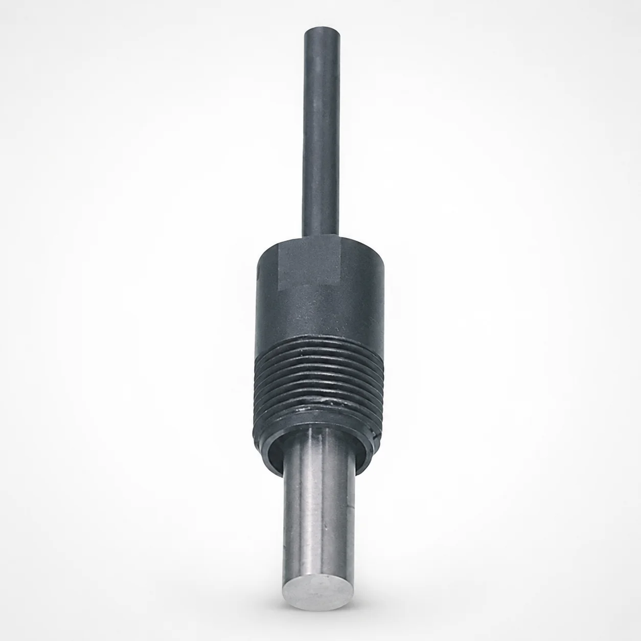
Runner Ejector Sets for Three-Plate Molds
Runner ejector sets for three-plate molds provide dependable runner removal by supporting smooth release during the molding cycle. Their engineered housing and ejector pin arrangement help maintain stable operation for consistent production.
- Three-plate mold runner ejection set designed for stable part release
- Modular composition supports Housing + Pin + Set configurations
- Built to handle runner ejection demands with wear-resistant construction
- Used in high-demand injection molding workflows requiring reliable ejection
Specifications
93 configurations available
| Product composition | P (Pin diameter) (mm) | B (Pin diameter length) (mm) | L (L dimension) (mm) | Coil springs | D (Housing outer diameter) (mm) | type |
|---|---|---|---|---|---|---|
| Set | 6 | 10 | 35 | WF | - | - |
| Set | 6 | 10 | 35 | WFH | - | - |
| Set | 6 | 10 | 35 | WL | - | - |
| Set | 6 | 10 | 35 | WLH | - | - |
| Set | 6 | 10 | 40 | WF | - | - |
| Set | 6 | 10 | 40 | WFH | - | - |
| Set | 6 | 10 | 40 | WL | - | - |
| Set | 6 | 10 | 40 | WLH | - | - |
| Set | 6 | 15 | 40 | WF | - | - |
| Set | 6 | 15 | 40 | WFH | - | - |
| Set | 6 | 15 | 40 | WL | - | - |
| Set | 6 | 15 | 40 | WLH | - | - |
| Set | 6 | 15 | 45 | WF | - | - |
| Set | 6 | 15 | 45 | WFH | - | - |
| Set | 6 | 15 | 45 | WL | - | - |
| Set | 6 | 15 | 45 | WLH | - | - |
| Set | 6 | 15 | 50 | WF | - | - |
| Set | 6 | 15 | 50 | WFH | - | - |
| Set | 6 | 15 | 50 | WL | - | - |
| Set | 6 | 15 | 50 | WLH | - | - |
| Set | 6 | 15 | 60 | WF | - | - |
| Set | 6 | 15 | 60 | WFH | - | - |
| Set | 6 | 15 | 60 | WL | - | - |
| Set | 6 | 15 | 60 | WLH | - | - |
| Set | 8 | 23 | 50 | WF | - | - |
| Set | 8 | 23 | 50 | WFH | - | - |
| Set | 8 | 23 | 50 | WL | - | - |
| Set | 8 | 23 | 50 | WLH | - | - |
| Set | 8 | 23 | 55 | WF | - | - |
| Set | 8 | 23 | 55 | WFH | - | - |
| Set | 8 | 23 | 55 | WL | - | - |
| Set | 8 | 23 | 55 | WLH | - | - |
| Set | 8 | 23 | 60 | WF | - | - |
| Set | 8 | 23 | 60 | WFH | - | - |
| Set | 8 | 23 | 60 | WL | - | - |
| Set | 8 | 23 | 60 | WLH | - | - |
| Set | 8 | 23 | 65 | WF | - | - |
| Set | 8 | 23 | 65 | WFH | - | - |
| Set | 8 | 23 | 65 | WL | - | - |
| Set | 8 | 23 | 65 | WLH | - | - |
| Set | 8 | 23 | 70 | WF | - | - |
| Set | 8 | 23 | 70 | WFH | - | - |
| Set | 8 | 23 | 70 | WL | - | - |
| Set | 8 | 23 | 70 | WLH | - | - |
| Set | 8 | 28 | 60 | WF | - | - |
| Set | 8 | 28 | 60 | WFH | - | - |
| Set | 8 | 28 | 60 | WL | - | - |
| Set | 8 | 28 | 60 | WLH | - | - |
| Set | 8 | 28 | 65 | WF | - | - |
| Set | 8 | 28 | 65 | WFH | - | - |
Product Guide
Application Scenarios+
Runner ejector sets are used in three-plate injection molds to ensure the sprue/runner system releases cleanly at the end of the molding cycle. In runner-specific tooling, the set supports consistent ejection by pairing a stable housing with a matched ejector pin and return spring configuration.
- Automotive connector and sensor housings: When runner balance and cycle repeatability are critical, the pin diameter options (P = 6, 8, 10 mm) and multiple pin lengths (B = 10 to 38 mm) help align ejection force with runner geometry.
- Consumer electronics injection parts: For thin-walled components, smooth runner removal reduces part drag risk; selecting the appropriate housing OD (D = 14, 16, 18 mm) supports stable mechanical guidance.
- Industrial enclosures and appliance components: Spring variants (WF/WFH/WL/WLH) allow tuning the return behavior for high-demand production.
This variant’s modular composition (Set, Housing, Pin) makes it easier to configure the exact runner ejection hardware needed for reliable ejection and long service life.
Material & Process Details+
The provided specifications define configuration and dimensions (P = 6, 8, 10 mm; D = 14, 16, 18 mm; lengths B and L), but they do not include a specific steel grade, hardness (HRC), or heat-treatment state. Therefore, material selection details such as whether the components are through-hardened, quenched & tempered, nitrided, or surface-treated cannot be confirmed from the input data.
In runner ejection hardware, engineers typically balance wear resistance (for frequent runner contacts and sliding) with toughness (to avoid chipping or bending under ejection loads). If you need a specific grade equivalency (e.g., H13, SKD61), please share the supplier material code or request documentation, and we can align the process and hardness targets to your application duty cycle.
Sizing & Selection Guide+
To select the correct runner ejector set for a three-plate mold, match the ejector pin and housing geometry to the runner ejection path and available space in the moving plate.
- Choose pin diameter (P): Select P = 6, 8, or 10 mm based on the required contact area and the runner bushing/gate layout.
- Set pin effective length (B): Use B = 10, 15, 23, 28, 33, or 38 mm so the pin travels far enough to release the runner without over-stressing the mechanism.
- Verify L dimension: Confirm L is within 35 ~ 85 mm to fit the plate thickness and stack-up for your mold design.
- Select housing OD (D): Use D = 14, 16, or 18 mm to ensure proper guidance clearance in the receiving block.
Because tolerance and fit values are not provided in the input data, maintain recommended clearance from your standard ejector-pin/guide practices and validate fit in the CAD stack-up for smooth travel.
Frequently Asked Questions
Which pin diameter (P = 6, 8, or 10 mm) should I use for runner ejection in a three-plate mold?+
How do I choose the pin length (B) from 10–38 mm for reliable runner removal?+
What does the L (35 ~ 85 mm) dimension control in the runner ejector set configuration?+
Can I configure the runner ejector set as Set, Housing, and Pin separately?+
How do coil spring codes (WF/WFH/WL/WLH) affect ejector performance?+
Need Custom Specifications?
Our engineering team can help with custom configurations, material selection, and volume pricing.