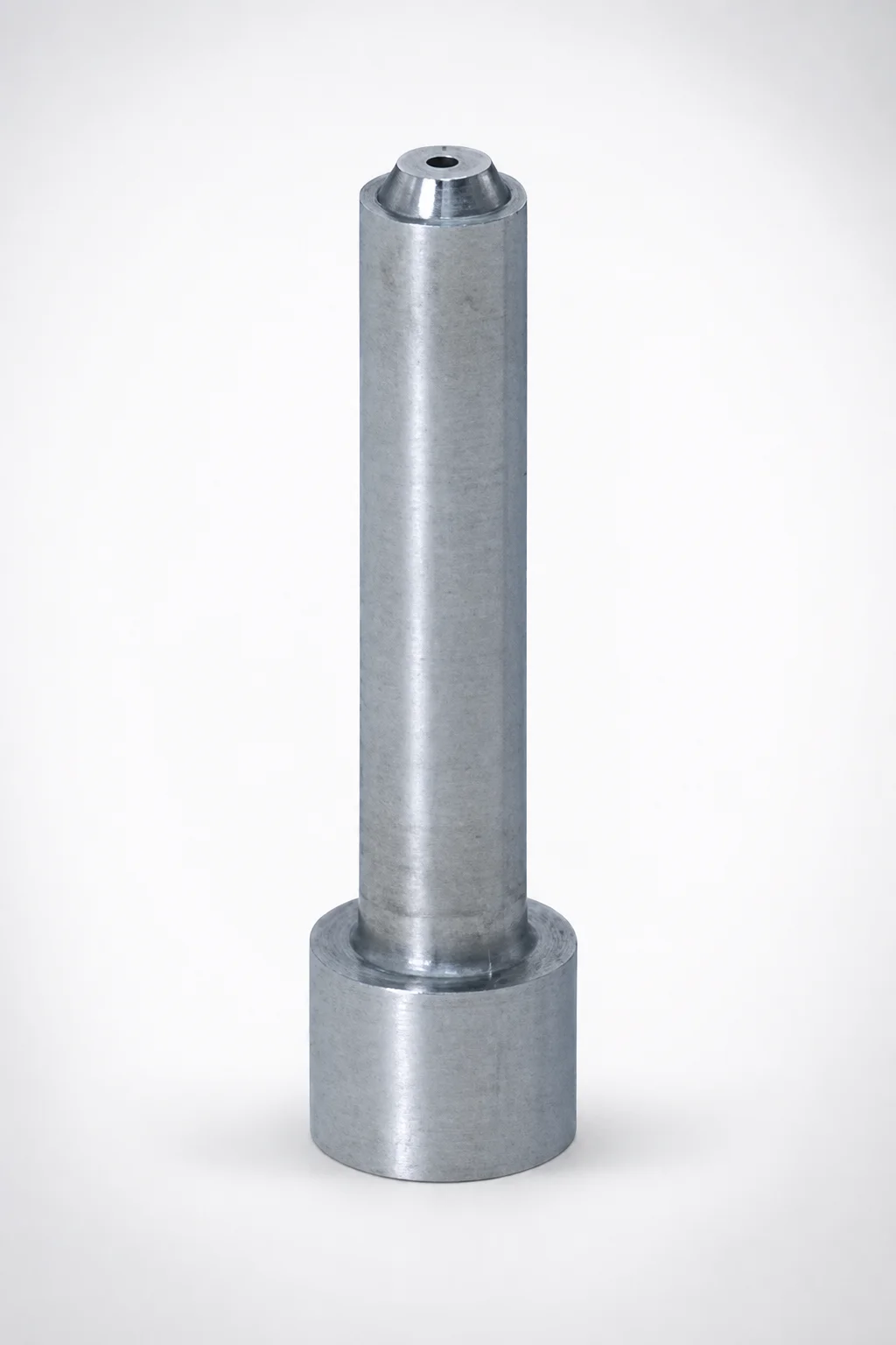
Carbide Pin-Point Gate Bushings SR Tip Step
Pin-point gate bushings (Carbide) with an SR tip step design provide a round gate transition for stable, repeatable gate formation. The precision carbide construction supports efficient molding with clean gate appearance across production runs.
- SR tip step geometry helps control sprue-to-gate flow for consistent gate size
- Carbide build offers strong wear resistance for longer bushing service life
- Round gate transition supports uniform filling during injection and minimizes flow disruption
- Compatible with pin-point gating setups; suitable for tooling that requires controlled tip features
Specifications
35 configurations available
| Tip Shape | D (Outer diameter) (mm) | A (Secondary sprue angle) (°) | B (Length excluding the lengths of head and tip) (mm) | C (Tip length) (mm) | K (Cutting angle) (°) | L (L dimension) (mm) | P (Tip diameter) (mm) | R (Tip R) (mm) | S (Tip angle) (°) | V (Tip diameter) (mm) | type |
|---|---|---|---|---|---|---|---|---|---|---|---|
| 1A | 2 | 1 ~ 3 | 3 ~ 5 | 0.2 ~ 0.4 | 20 ~ 30 | 6 ~ 20 | 0.3 ~ 0.5 | - | - | 1.3 ~ 1.9 | - |
| 1A | 2.5 | 1 ~ 3 | 4 ~ 6 | 0.2 ~ 0.5 | 20 ~ 30 | 8 ~ 25 | 0.3 ~ 0.6 | - | - | 1.5 ~ 2.4 | - |
| 1A | 3 | 1 ~ 3 | 5 ~ 9 | 0.3 ~ 0.8 | 20 ~ 30 | 10 ~ 40 | 0.5 ~ 0.8 | - | - | 2 ~ 2.9 | - |
| 1A | 4 | 1 ~ 3 | 5 ~ 30 | 0.3 ~ 0.8 | 20 ~ 30 | 10 ~ 40 | 0.6 ~ 1 | - | - | 2.5 ~ 3.9 | - |
| 1A | 5 | 1 ~ 3 | 5 ~ 35 | 0.5 ~ 1.5 | 20 ~ 30 | 15 ~ 40 | 0.8 ~ 1.2 | - | - | 3.5 ~ 4.9 | - |
| 1A | 6 | 1 ~ 3 | 5 ~ 30 | 0.5 ~ 1.5 | 20 ~ 30 | 15 ~ 40 | 1 ~ 1.5 | - | - | 4 ~ 5.9 | - |
| 1A | 8 | 1 ~ 3 | 5 ~ 30 | 0.5 ~ 1.5 | 20 ~ 30 | 15 ~ 40 | 1.2 ~ 1.6 | - | - | 4.5 ~ 7.9 | - |
| 2A | 2 | 1 ~ 3 | 3 ~ 5 | - | 20 ~ 30 | 6 ~ 20 | 0.3 ~ 0.5 | - | - | - | - |
| 2A | 2.5 | 1 ~ 3 | 4 ~ 6 | - | 20 ~ 30 | 8 ~ 25 | 0.3 ~ 0.6 | - | - | - | - |
| 2A | 3 | 1 ~ 3 | 5 ~ 9 | - | 20 ~ 30 | 10 ~ 40 | 0.5 ~ 0.8 | - | - | - | - |
| 2A | 4 | 1 ~ 3 | 5 ~ 30 | - | 20 ~ 30 | 10 ~ 40 | 0.6 ~ 1 | - | - | - | - |
| 2A | 5 | 1 ~ 3 | 5 ~ 35 | - | 20 ~ 30 | 15 ~ 40 | 0.8 ~ 1.2 | - | - | - | - |
| 2A | 6 | 1 ~ 3 | 5 ~ 30 | - | 20 ~ 30 | 15 ~ 40 | 1 ~ 1.5 | - | - | - | - |
| 2A | 8 | 1 ~ 3 | 5 ~ 30 | - | 20 ~ 30 | 15 ~ 40 | 1.2 ~ 1.6 | - | - | - | - |
| 3A | 2 | 1 ~ 3 | 3 ~ 5 | 0.2 ~ 0.4 | 20 ~ 30 | 6 ~ 20 | 0.3 ~ 0.5 | - | 1 ~ 45 | - | - |
| 3A | 2.5 | 1 ~ 3 | 4 ~ 6 | 0.2 ~ 0.5 | 20 ~ 30 | 8 ~ 25 | 0.3 ~ 0.6 | - | 1 ~ 45 | - | - |
| 3A | 3 | 1 ~ 3 | 5 ~ 9 | 0.3 ~ 0.8 | 20 ~ 30 | 10 ~ 40 | 0.5 ~ 0.8 | - | 1 ~ 45 | - | - |
| 3A | 4 | 1 ~ 3 | 5 ~ 30 | 0.3 ~ 0.8 | 20 ~ 30 | 10 ~ 40 | 0.6 ~ 1 | - | 1 ~ 45 | - | - |
| 3A | 5 | 1 ~ 3 | 5 ~ 35 | 0.5 ~ 1.5 | 20 ~ 30 | 15 ~ 40 | 0.8 ~ 1.2 | - | 1 ~ 45 | - | - |
| 3A | 6 | 1 ~ 3 | 5 ~ 30 | 0.5 ~ 1.5 | 20 ~ 30 | 15 ~ 40 | 1 ~ 1.5 | - | 1 ~ 50 | - | - |
| 3A | 8 | 1 ~ 3 | 5 ~ 30 | 0.5 ~ 1.5 | 20 ~ 30 | 15 ~ 40 | 1.2 ~ 1.6 | - | 1 ~ 60 | - | - |
| 4A | 2 | 1 ~ 3 | 3 ~ 5 | 0.2 ~ 0.4 | 20 ~ 30 | 6 ~ 20 | 0.3 ~ 0.5 | 0.4 ~ 0.8 | - | - | - |
| 4A | 2.5 | 1 ~ 3 | 4 ~ 6 | 0.2 ~ 0.5 | 20 ~ 30 | 8 ~ 25 | 0.3 ~ 0.6 | 0.6 ~ 1 | - | - | - |
| 4A | 3 | 1 ~ 3 | 5 ~ 9 | 0.3 ~ 0.8 | 20 ~ 30 | 10 ~ 40 | 0.5 ~ 0.8 | 0.8 ~ 1.5 | - | - | - |
| 4A | 4 | 1 ~ 3 | 5 ~ 30 | 0.3 ~ 0.8 | 20 ~ 30 | 10 ~ 40 | 0.6 ~ 1 | 0.8 ~ 1.5 | - | - | - |
| 4A | 5 | 1 ~ 3 | 5 ~ 35 | 0.5 ~ 1.5 | 20 ~ 30 | 15 ~ 40 | 0.8 ~ 1.2 | 1 ~ 2 | - | - | - |
| 4A | 6 | 1 ~ 3 | 5 ~ 30 | 0.5 ~ 1.5 | 20 ~ 30 | 15 ~ 40 | 1 ~ 1.5 | 1.5 ~ 3 | - | - | - |
| 4A | 8 | 1 ~ 3 | 5 ~ 30 | 0.5 ~ 1.5 | 20 ~ 30 | 15 ~ 40 | 1.2 ~ 1.6 | 2 ~ 4 | - | - | - |
| 5A | 2 | 1 ~ 3 | 3 ~ 5 | 0.2 ~ 0.4 | 20 ~ 30 | 6 ~ 20 | 0.3 ~ 0.5 | - | - | - | - |
| 5A | 2.5 | 1 ~ 3 | 4 ~ 6 | 0.2 ~ 0.5 | 20 ~ 30 | 8 ~ 25 | 0.3 ~ 0.6 | - | - | - | - |
| 5A | 3 | 1 ~ 3 | 5 ~ 9 | 0.3 ~ 0.8 | 20 ~ 30 | 10 ~ 40 | 0.5 ~ 0.8 | - | - | - | - |
| 5A | 4 | 1 ~ 3 | 5 ~ 30 | 0.3 ~ 0.8 | 20 ~ 30 | 10 ~ 40 | 0.6 ~ 1 | - | - | - | - |
| 5A | 5 | 1 ~ 3 | 5 ~ 35 | 0.5 ~ 1.5 | 20 ~ 30 | 15 ~ 40 | 0.8 ~ 1.2 | - | - | - | - |
| 5A | 6 | 1 ~ 3 | 5 ~ 30 | 0.5 ~ 1.5 | 20 ~ 30 | 15 ~ 40 | 1 ~ 1.5 | - | - | - | - |
| 5A | 8 | 1 ~ 3 | 5 ~ 30 | 0.5 ~ 1.5 | 20 ~ 30 | 15 ~ 40 | 1.2 ~ 1.6 | - | - | - | - |
Product Guide
Application Scenarios+
Pin-point gate bushings are used in injection mold tooling where controlled, repeatable gate formation is required at the part interface. This SR tip step variant is designed to create a round gate transition that supports stable sprue-to-gate flow, helping maintain consistent gate geometry over production cycles.
- Automotive and industrial connector molds: Use this bushing style to achieve a clean pin-point gate appearance and reduce flow disruption, supporting reliable fill and repeatable gate size for multi-cavity or high-cycle layouts.
- Appliance and housings (thin-to-medium wall): The SR step assists in managing flow convergence while the carbide construction helps resist wear from repeated gate forming, supporting long service life during sustained runs.
- Medical device housings and precision parts: The controlled tip features (including selectable tip shapes and dimensions) help tune the gate region for lower variability in gate remnants and consistent part ejection and finishing.
Selection is suited to applications needing controlled tip geometry and a round transition to stabilize gate formation under changing melt viscosities and cavity loading.
Material & Process Details+
This product is specified as a carbide pin-point gate bushing, leveraging carbide’s high hardness and strong wear resistance at the hot, abrasive gate-forming interface. Carbide tools typically prioritize wear resistance and dimensional stability, which helps maintain the SR tip step geometry for consistent gate formation across production runs.
- Wear resistance: High hardness at the gate region reduces erosion and tip wear, supporting stable gate appearance.
- Toughness trade-off: Compared with tougher mold steels, carbide is generally less tolerant of impact or shock; avoid designs that expose the tip to sudden mechanical loads.
- Manufacturing process (typical for carbide inserts): Carbide blanks are precision-machined to the selected tip profile (SR tip step), followed by finishing/precision grinding to achieve the required tip radii and angles.
Heat treatment state is not specified in the provided data; carbide is typically supplied as a sintered and precision-ground component rather than by post-quench tempering like tool steels.
Sizing & Selection Guide+
To select the correct bushing, match the outer diameter (D) and the functional tip dimensions to your gate bushing pocket and the desired pin-point gate size at the cavity.
- Outer fit: Choose D (2–8 mm) to match the gate insert/runner interface. Confirm pocket dimensions and clearance so the bushing seats without interference.
- Gate geometry: Tune P (tip diameter, 0.3–1.2 mm), V (tip diameter, 1.3–4.5 mm), R (tip radius, 0.4–8.0 mm in the provided ranges), and S (tip angle, 1–45°/50°/60° per option) to achieve the target gate size and tip curvature for stable filling.
- Tip and overall placement: Select C (tip length, 0.2–0.4/0.2–0.5/0.3–0.8/0.5–1.5 mm) and B (length excluding head/tip, 3–5, 4–6, 5–9, 5–30, 5–35 mm) to position the SR step correctly relative to the sprue-to-gate transition.
- Fixed angles: A (1–3°) and K (20–30°) are fixed; verify they align with your gate bush design intent. Tip Shape options are selectable: 1A, 2A, 3A, 4A, 5A.
Because these are parameterized variants, treat dimensions as model-specific—confirm the full set (D, B, C, L, P, R, S, V, and tip shape) for compatibility with the cavity insert and gate cutting features.
Frequently Asked Questions
How do I select the correct SR tip step geometry (Tip Shape 1A–5A) for a stable pin-point gate?+
What should I match first: outer diameter D (2–8 mm) or tip diameter P (0.3–1.2 mm)?+
How do B (length excluding head/tip) and C (tip length) affect the SR step positioning in the mold?+
Which dimensions control the curvature of the gate tip: R (tip R) or S (tip angle)?+
Is this carbide SR tip bushing suitable for high-cycle wear-critical gating, and what are the material trade-offs?+
Related Products
Need Custom Specifications?
Our engineering team can help with custom configurations, material selection, and volume pricing.