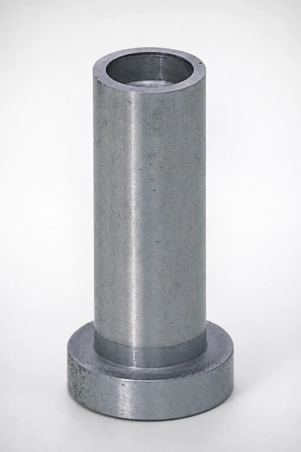
Pin Gate Extension Bushings M2/P21 Steel
Pin Gate Extension Bushings (M2/P21 steel) are engineered to support consistent gate positioning and stable motion during manufacturing and assembly. Their durable construction helps reduce wear while protecting sensitive systems without reducing cycle performance.
- Extension bushing design improves stability and smooth movement under load
- Built from M2/P21 steel for strong wear resistance and long service life
- Supports reliable fit-in operations for repeatable alignment during production
- Used in gate extension and precision assembly processes requiring dependable support
Specifications
48 configurations available
| Type | Material | D (Outer diameter) (mm) | A (Taper angle) (mm) | L (L dimension) (mm) | V (Tip diameter) (mm) | VC (V dimension alteration) (mm) | type |
|---|---|---|---|---|---|---|---|
| Head type | SKH51 | 6 | 1 ~ 2 | 10 ~ 40 | 1.5 ~ 2.5 | - | - |
| Head type | SKH51 | 6 | 1 ��� 2 | 10 ~ 40 | - | 1.5 ~ 3.5 | - |
| Head type | SKH51 | 8 | 1 ~ 3 | 10 ~ 40 | 2 ~ 3.5 | - | - |
| Head type | SKH51 | 8 | 1 ~ 3 | 10 ~ 40 | - | 1.5 ~ 5 | - |
| Head type | SKH51 | 10 | 1 ~ 3 | 10 ~ 40 | 3 ~ 5 | - | - |
| Head type | SKH51 | 10 | 1 ~ 3 | 10 ~ 40 | - | 1.5 ~ 7 | - |
| Head type | SKH51 | 13 | 1 ~ 3 | 10 ~ 40 | 4.5 ~ 7 | - | - |
| Head type | SKH51 | 13 | 1 ~ 3 | 10 ~ 40 | - | 1.5 ~ 6.9 | - |
| Head type・Reverse tapered type | SKH51 | 6 | 1 ~ 2 | 10 ~ 40 | 1.5 ~ 2.5 | - | - |
| Head type・Reverse tapered type | SKH51 | 6 | 1 ~ 2 | 10 ~ 40 | - | 1.5 ~ 3.5 | - |
| Head type・Reverse tapered type | SKH51 | 8 | 1 ~ 3 | 10 ~ 40 | 2 ~ 3.5 | - | - |
| Head type・Reverse tapered type | SKH51 | 8 | 1 ~ 3 | 10 ~ 40 | - | 1.5 ~ 5 | - |
| Head type・Reverse tapered type | SKH51 | 10 | 1 ~ 3 | 10 ~ 40 | 3 ~ 5 | - | - |
| Head type・Reverse tapered type | SKH51 | 10 | 1 ~ 3 | 10 ~ 40 | - | 1.5 ~ 7 | - |
| Head type・Reverse tapered type | SKH51 | 13 | 1 ~ 3 | 10 ~ 40 | 4.5 ~ 7 | - | - |
| Head type・Reverse tapered type | SKH51 | 13 | 1 ~ 3 | 10 ~ 40 | - | 1.5 ~ 6.9 | - |
| Headless type | SKH51 | 6 | 1 ~ 2 | 10 ~ 40 | 1.5 ~ 2.5 | - | - |
| Headless type | SKH51 | 6 | 1 ~ 2 | 10 ~ 40 | - | 1.5 ~ 3.5 | - |
| Headless type | SKH51 | 8 | 1 ~ 3 | 10 ~ 40 | 2 ~ 3.5 | - | - |
| Headless type | SKH51 | 8 | 1 ~ 3 | 10 ~ 40 | - | 1.5 ~ 5 | - |
| Headless type | SKH51 | 10 | 1 ~ 3 | 10 ~ 40 | 3 ~ 5 | - | - |
| Headless type | SKH51 | 10 | 1 ~ 3 | 10 ~ 40 | - | 1.5 ~ 7 | - |
| Headless type | SKH51 | 13 | 1 ~ 3 | 10 ~ 40 | 4.5 ~ 7 | - | - |
| Headless type | SKH51 | 13 | 1 ~ 3 | 10 ~ 40 | - | 1.5 ~ 6.9 | - |
| Head type | NAK80 | 6 | 1 ~ 2 | 10 ~ 40 | 1.5 ~ 2.5 | - | - |
| Head type | NAK80 | 6 | 1 ~ 2 | 10 ~ 40 | - | 1.5 ~ 3.5 | - |
| Head type | NAK80 | 8 | 1 ~ 3 | 10 ~ 40 | 2 ~ 3.5 | - | - |
| Head type | NAK80 | 8 | 1 ~ 3 | 10 ~ 40 | - | 1.5 ~ 5 | - |
| Head type | NAK80 | 10 | 1 ~ 3 | 10 ~ 40 | 3 ~ 5 | - | - |
| Head type | NAK80 | 10 | 1 ~ 3 | 10 ~ 40 | - | 1.5 ~ 7 | - |
| Head type | NAK80 | 13 | 1 ~ 3 | 10 ~ 40 | 4.5 ~ 7 | - | - |
| Head type | NAK80 | 13 | 1 ~ 3 | 10 ~ 40 | - | 1.5 ~ 6.9 | - |
| Head type・Reverse tapered type | NAK80 | 6 | 1 ~ 2 | 10 ~ 40 | 1.5 ~ 2.5 | - | - |
| Head type・Reverse tapered type | NAK80 | 6 | 1 ~ 2 | 10 ~ 40 | - | 1.5 ~ 3.5 | - |
| Head type・Reverse tapered type | NAK80 | 8 | 1 ~ 3 | 10 ~ 40 | 2 ~ 3.5 | - | - |
| Head type・Reverse tapered type | NAK80 | 8 | 1 ~ 3 | 10 ~ 40 | - | 1.5 ~ 5 | - |
| Head type・Reverse tapered type | NAK80 | 10 | 1 ~ 3 | 10 ~ 40 | 3 ~ 5 | - | - |
| Head type・Reverse tapered type | NAK80 | 10 | 1 ~ 3 | 10 ~ 40 | - | 1.5 ~ 7 | - |
| Head type・Reverse tapered type | NAK80 | 13 | 1 ~ 3 | 10 ~ 40 | 4.5 ~ 7 | - | - |
| Head type・Reverse tapered type | NAK80 | 13 | 1 ~ 3 | 10 ~ 40 | - | 1.5 ~ 6.9 | - |
| Headless type | NAK80 | 6 | 1 ~ 2 | 10 ~ 40 | 1.5 ~ 2.5 | - | - |
| Headless type | NAK80 | 6 | 1 ~ 2 | 10 ~ 40 | - | 1.5 ~ 3.5 | - |
| Headless type | NAK80 | 8 | 1 ~ 3 | 10 ~ 40 | 2 ~ 3.5 | - | - |
| Headless type | NAK80 | 8 | 1 ~ 3 | 10 ~ 40 | - | 1.5 ~ 5 | - |
| Headless type | NAK80 | 10 | 1 ~ 3 | 10 ~ 40 | 3 ~ 5 | - | - |
| Headless type | NAK80 | 10 | 1 ~ 3 | 10 ~ 40 | - | 1.5 ~ 7 | - |
| Headless type | NAK80 | 13 | 1 ~ 3 | 10 ~ 40 | 4.5 ~ 7 | - | - |
| Headless type | NAK80 | 13 | 1 ~ 3 | 10 ~ 40 | - | 1.5 ~ 6.9 | - |
Product Guide
Application Scenarios+
Pin gate extension bushings are used in injection mold tooling to maintain accurate gate alignment between the sprue/gate components and the gate-forming insert. In assembly stages, the extension geometry stabilizes positioning and supports repeatable, smooth movement under load, helping prevent drift that can affect gate thickness and downstream weld formation.
- Automotive connector and terminal molds: The bushings’ stable fit-in operation supports consistent gate placement across high-repeat runs, which helps reduce variation in gate vestige and flow behavior.
- Electronics and small housing gates: By resisting wear during frequent maintenance and part insert changes, this variant helps protect sensitive gate interfaces while maintaining movement reliability.
- Precision multi-cavity systems: Tapered or head-specific types improve guiding during alignment, supporting reliable stack-up control when tolerances are tight.
Available steel options (notably M2/P21-equivalent SKH51 or NAK80) are selected for strong wear resistance and dependable motion performance where gate support surfaces experience repeated contact.
Material & Process Details+
This series is offered in SKH51 and NAK80, enabling selection based on wear and toughness needs. SKH51 corresponds to the AISI M2 family of high-speed steels and is typically chosen for high wear resistance where gate support surfaces are repeatedly loaded.
- SKH51 (AISI M2 equivalent): Strong abrasive/wear performance with a hardness often in the high-HRC range; ideal for long life under frequent sliding/positioning cycles.
- NAK80: Commonly used for molds requiring balanced performance; generally emphasizes dimensional stability and toughness compared with more wear-focused tool steels.
Heat treatment is typically provided in a hardened and tempered state for these tool steels (exact HRC and process details depend on the supplier’s standard for the selected material and head type). Expect a trade-off between maximum hardness for wear resistance and toughness for resistance to chipping when selecting the steel option.
Sizing & Selection Guide+
To select the correct pin gate extension bushing, match the interface dimensions to the mold’s gate/support stack-up and alignment surfaces. Use the provided ranges to choose the outer diameter D = 6, 8, 10, or 13 mm first; this must correspond to the bushing bore/guide feature in the mold base or gate system.
- Length L: fixed at 10–40 mm. Choose L to span the required support depth and ensure stable engagement without over-constraining movement.
- Taper angle A: available at 1–2 mm, 1–2 (alternate), and 1–3 mm (as listed). Select A to suit the guiding/centering behavior required during assembly.
- Tip diameter V: choose from the provided tip ranges 1.5–2.5, 2–3.5, 3–5, or 4.5–7 mm based on the mating gate interface geometry.
- VC (V dimension alteration): select from 1.5–3.5, 1.5–5, 1.5–7, or 1.5–6.9 mm to achieve the desired clearance/fit compensation.
When integrating into a mold cavity/core, prioritize tolerance stack-up: V/VC governs the effective tip engagement, so verify clearances against your cavity alignment tolerances and planned wear allowances.
Frequently Asked Questions
Which steel option (SKH51 vs NAK80) is better for wear resistance on gate support surfaces?+
SKH51 (AISI M2 equivalent family) is generally selected when maximum wear resistance is the primary requirement because it belongs to high-performance tool steels. NAK80 is typically chosen for a more balanced performance approach where toughness and stability are valued alongside wear behavior. Choose based on your expected sliding/contact frequency and the acceptable risk of chipping versus surface wear.
How do I choose the correct outer diameter D and length L to match my mold’s gate extension bore?+
Select D first from the available options: 6, 8, 10, or 13 mm, ensuring it matches the guide/bushing bore diameter in your mold. Then choose L within 10–40 mm to cover the required support depth for stable gate alignment without excessive over-travel. Confirm tolerance stack-up between the bushing, mating guide, and gate insert to maintain repeatable fit-in alignment.
What do the taper angle A, tip diameter V, and VC values control during assembly alignment?+
The taper angle A (listed as 1–2 mm or 1–3 mm depending on variant) controls how the bushing centers and guides during insertion. The tip diameter V (ranges from 1.5–2.5 up to 4.5–7 mm) sets the functional engagement size at the gate interface. VC (from 1.5–3.5, 1.5–5, 1.5–7, or 1.5–6.9 mm) provides alteration/compensation for the effective fit, so use VC to tune clearance and wear allowance.
Can I use head type, reverse tapered type, or headless type interchangeably on a gate extension system?+
They are not interchangeable without verifying your mold’s assembly stack-up. The provided type options (head type, reverse tapered type, headless type) affect how the bushing is guided, retained, and how it transitions during insertion. Match the type to your mold’s corresponding features so the bushing maintains stable gate positioning and reliable movement under load.
What sizing mistakes most commonly cause misalignment or poor movement reliability?+
Most issues come from mismatching D to the guide bore and selecting V/VC that do not achieve the intended engagement and clearance. Also verify L is long enough to provide stable support but not so long that it interferes with movement. Finally, choose A to match your centering requirement during assembly; an incorrect taper can increase insertion force and accelerate wear.
Related Products
Need Custom Specifications?
Our engineering team can help with custom configurations, material selection, and volume pricing.