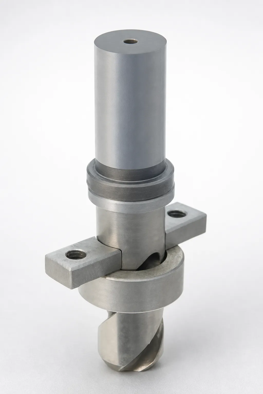
MRGC In-Mold Rolling Gate Cut Units
MRGC In-Mold Rolling Gate Cut Units deliver reliable security and smooth access control through precise in-mold operation. Built from robust steel components, they help maintain stable performance and reduce downtime in demanding industrial settings.
- MRGC rolling gate cut unit type designed for consistent in-mold cycling
- Robust steel construction supports durable operation under repeated use
- Precision engineering promotes smooth gate action for reliable control
- Suitable for commercial and industrial equipment requiring controlled access
Specifications
5 configurations available
| D (Outer diameter) (mm) | LA (mm) | LAC (LA dimension alteration) (mm) | LB (mm) | type |
|---|---|---|---|---|
| 16 | 40 | - | 60 | - |
| 16 | - | 25 ~ 39.99 | 60 | - |
| 20 | 40 ~ 60 | - | 80 | - |
| 20 | - | 35 ~ 39.99 | 80 | - |
| 20 | - | 40.01 ~ 59.99 | 80 | - |
Product Guide
Application Scenarios+
Where it’s used: This in-mold rolling gate cut unit is installed in injection mold tooling to control how a gate is opened/closed during cycle. Its in-mold operation is designed for repeatable actuation, helping maintain consistent access and reducing timing-related scrap.
- Industrial control equipment housings: Use it when gate access must be reliable over many cycles; the unit’s robust steel construction supports durable performance in production environments.
- Automotive and electronics component gating: In applications where gate appearance and flow control affect final part quality, the precision rolling-gate action supports smooth gate behavior for dependable control.
- Commercial machinery parts: When downtime is costly, the consistent in-mold cycling capability helps stabilize manufacturing output across repeated runs.
Why this variant fits: The MRGC rolling gate cut unit type is suited for tooling that benefits from stable, precise in-mold cycling and smooth gate action under repeated use.
Material & Process Details+
Steel and heat treatment: The provided product data specifies a robust steel design for durable, repeated in-mold cycling. However, no exact steel grade, hardness (HRC), or specific heat-treatment condition (e.g., quenched & tempered, nitrided) is listed in the available specifications.
What to consider in selection: For rolling gate mechanisms, materials must balance wear resistance for sliding contact and toughness to tolerate shock loads during actuation. When comparing options, harder conditions typically improve wear resistance but can reduce toughness if overly brittle—so the final specification should be aligned with your expected cycle rate and load profile.
- Wear resistance: important for smooth gate motion over repeated cycles
- Toughness: supports durability under intermittent impact
- Heat-treatment state: confirm with supplier drawings if you require a specific HRC target
Sizing & Selection Guide+
Start with outer diameter (D): Select the unit variant by matching the outer diameter to your mold gate-cutting mechanism space. Available D values are 16 mm or 20 mm.
Match the actuation geometry: The unit length is defined by LA, with options of 40 mm or 40–60 mm. Ensure the available stroke length in the mold design accommodates the selected LA.
- LAC (LA alteration): Available ranges are 25–39.99 mm, 35–39.99 mm, and 40.01–59.99 mm. Choose the LAC range that corresponds to your molded component’s required dimensional change during actuation.
- LB: Available values are 60 mm or 80 mm. Match LB to the mounting/support envelope and clearance to adjacent tooling.
Tolerance/fit note: Since no tolerance values are provided in the input data, verify fit by comparing your CAD clearances and assembly drawings for the chosen D and LA/LAC combination, especially for moving/rolling interfaces.
Frequently Asked Questions
How do I choose the correct D (outer diameter) for MRGC rolling gate cut units in my mold?+
Select based on the available envelope for the gate-cut/rolling mechanism: MRGC variants are offered with D = 16 mm or D = 20 mm. Confirm that the housing bore and surrounding steel provide the required clearance for assembly and motion. Use the D selection first, then validate LA/LAC against your gate-actuation stroke.
What is the relationship between LA and LAC when configuring the cut unit geometry?+
The input data provides LA options of 40 mm or 40–60 mm, and separate LAC ranges of 25–39.99 mm, 35–39.99 mm, or 40.01–59.99 mm. In practice, LAC is used to define the dimensional alteration tied to how the unit’s action matches your mold’s requirements. Choose the LAC range that corresponds to the dimensional change you expect within the chosen LA.
Which LB length should I select for mounting and support in the mold assembly?+
MRGC units are available with LB = 60 mm or LB = 80 mm. Select LB to match your mounting/support space and ensure the unit can be assembled without interference. After LB selection, re-check that LA/LAC still fit the actuation geometry and stroke path.
Is there a specified steel grade or hardness (HRC) for this MRGC cut unit series?+
The current product data states a robust steel construction, but it does not list an exact steel grade, heat-treatment condition, or hardness target (HRC). If your design requires a specific wear resistance/toughness profile, request the detailed material spec and heat-treatment data from the supplier documentation. That will confirm suitability for your cycle rate and contact loads.
What tolerances should I assume for fitting the moving rolling-gate components?+
No tolerance values are provided in the available specifications for D, LA, LAC, or LB. For design assurance, validate clearances using your mold CAD and the official drawing package for the chosen MRGC variant. Pay special attention to fit at the rolling/sliding interfaces since those affect smooth gate action over repeated cycles.
Related Products
Need Custom Specifications?
Our engineering team can help with custom configurations, material selection, and volume pricing.