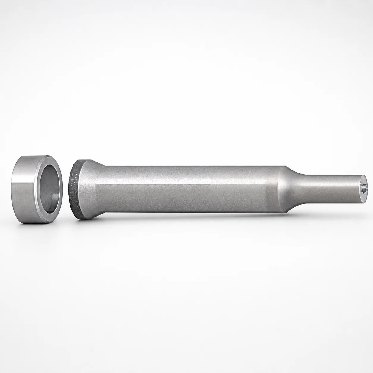
Tapered Head Ejector Punches WPC Treatment
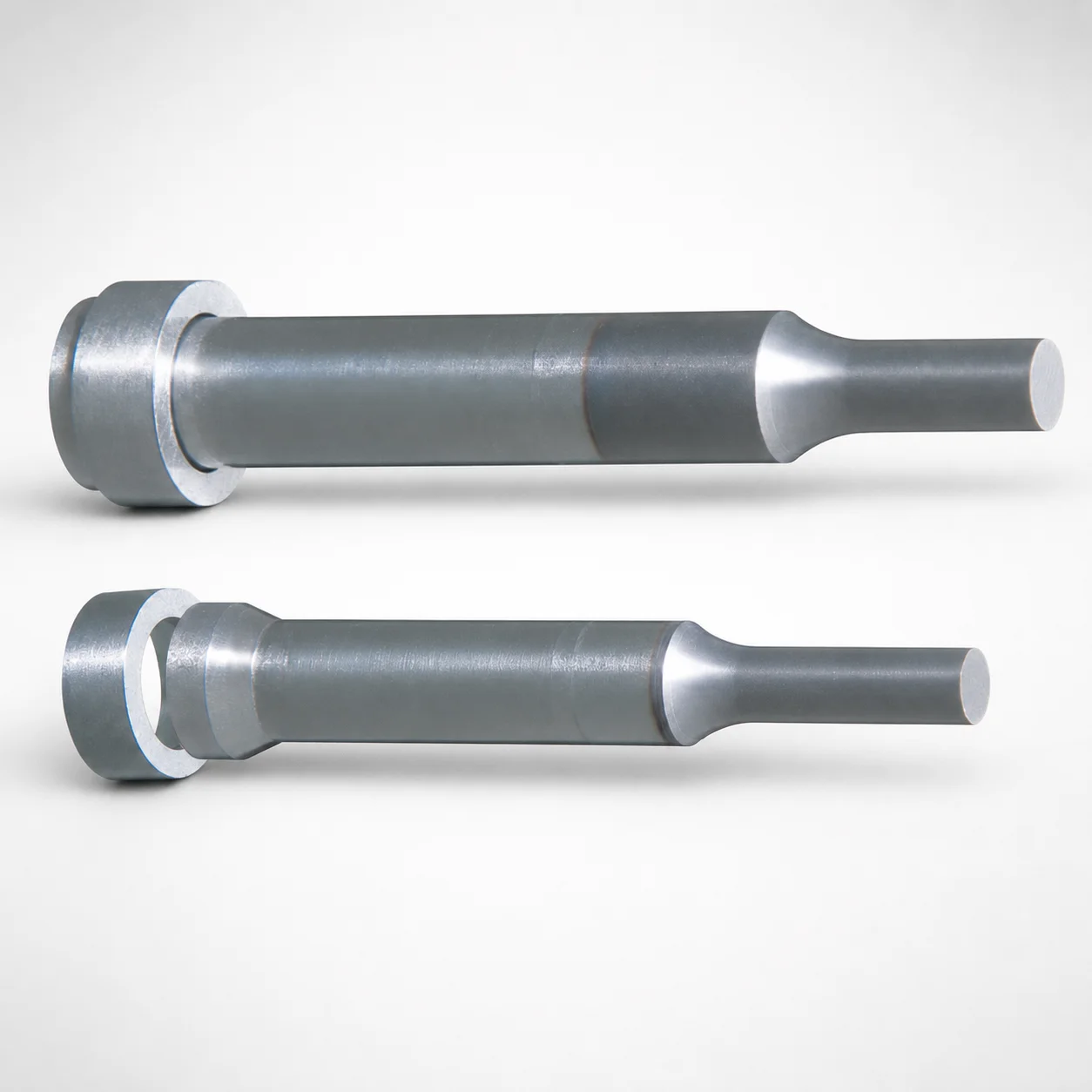
Tapered Head Ejector Punches WPC Treatment are built for heavy-load tooling to support stable ejection in demanding molding and press operations. The tapered head design and WPC surface treatment help resist wear while maintaining dependable punch performance.
- Single-stepped shank for consistent guidance under load and stable alignment
- Standard-type ejector geometry with Tip shape A for predictable ejection behavior
- WPC surface treatment improves wear resistance for longer tool life
- Typical for die sets requiring heavy-load punch action and repeatable ejection
Specifications
16 configurations available
| Material | B (Tip length) | D (Shank diameter) (mm) | P (Tip dimension) (mm) | L (L dimension) (mm) | type |
|---|---|---|---|---|---|
| Powdered high-speed steel | L | 8 | 4 ~ 7.99 | 60 ~ 80 | - |
| Powdered high-speed steel | L | 10 | 5 ~ 9.99 | 60 ~ 90 | - |
| Powdered high-speed steel | L | 13 | 6 ~ 12.99 | 70 ~ 100 | - |
| Powdered high-speed steel | L | 16 | 10 ~ 15.99 | 70 ~ 100 | - |
| Powdered high-speed steel | S | 8 | 4 ~ 7.99 | 50 ~ 80 | - |
| Powdered high-speed steel | S | 10 | 5 ~ 9.99 | 55 ~ 90 | - |
| Powdered high-speed steel | S | 13 | 6 ~ 12.99 | 65 ~ 100 | - |
| Powdered high-speed steel | S | 16 | 10 ~ 15.99 | 65 ~ 100 | - |
| SKH51 Equivalent | L | 8 | 4 ~ 7.99 | 60 ~ 80 | - |
| SKH51 Equivalent | L | 10 | 5 ~ 9.99 | 60 ~ 90 | - |
| SKH51 Equivalent | L | 13 | 6 ~ 12.99 | 70 ~ 100 | - |
| SKH51 Equivalent | L | 16 | 10 ~ 15.99 | 70 ~ 100 | - |
| SKH51 Equivalent | S | 8 | 4 ~ 7.99 | 50 ~ 80 | - |
| SKH51 Equivalent | S | 10 | 5 ~ 9.99 | 55 ~ 90 | - |
| SKH51 Equivalent | S | 13 | 6 ~ 12.99 | 65 ~ 100 | - |
| SKH51 Equivalent | S | 16 | 10 ~ 15.99 | 65 ~ 100 | - |
Product Guide
Application Scenarios+
These tapered-head ejector punches are used in injection mold and die tooling where consistent ejection force and wear resistance are required. The tapered head geometry helps guide the punch during stroke, supporting stable contact in heavy-load ejection applications such as automotive connector housings and under-hood component molding.
In appliance and industrial enclosure tooling, the single-stepped shank improves guidance and alignment under repeated press cycles, which helps reduce vibration and uneven wear during ejector operation.
For die sets with frequent cycle times—where ejector tips experience sliding and impact—this variant’s WPC surface treatment is suited to improve wear life while maintaining reliable punch performance with standard tip geometry (Tip shape A).
- Automotive connector and housing molds: tapered head for stable guided ejection.
- Industrial enclosure/consumer appliance molds: stepped shank for consistent alignment under load.
- High-cycle die sets: WPC treatment to resist tip wear for longer service life.
Material & Process Details+
The punches are made from powdered high-speed steel with an SKH51-equivalent grade (commonly referenced as an AISI M2-equivalent class in high-speed steel families). Powder metallurgy helps refine carbides, supporting improved wear behavior for ejector applications.
With WPC surface treatment, the design targets enhanced wear resistance at the punch working areas while retaining the base steel’s toughness for repeated strokes. Compared with more general-purpose tool steels, high-speed steel offers better resistance to abrasion and thermal effects during frequent molding cycles.
- Heat treatment state: specified as SKH51-equivalent high-speed steel; final hardness is not provided in the data, so users should confirm the supplied heat-treatment condition with the tool build sheet.
- Wear vs. toughness: optimized for abrasive tip wear; excessive loads may still require cavity/core wear management.
Sizing & Selection Guide+
Select the ejector punch dimensions to match the mold’s ejector plate spacing and the required penetration path through the core/cavity. Your configuration must fit both the shank diameter (D) and the available opening/guide clearance in the mold.
- Shank diameter (D): choose one of 8, 10, 13, or 16 mm to match the ejector bore/guide constraints.
- Tip length (B): select from the provided L/S ranges (tip length options correspond to the series’ variable B).
- Tip dimension (P): match the required standard tip geometry size using the ranges: 4–7.99, 5–9.99, 6–12.99, or 10–15.99 mm.
The L (overall length) must cover the full travel and engagement needed for ejection. Available L ranges include 60–80, 60–90, 70–100, 50–80, 55–90, and 65–100 mm; select the shortest length that still ensures stable contact through the ejector stroke. Tolerance and fit are governed by the mold’s guiding system; ensure sufficient clearance around D for installation and thermal expansion.
Frequently Asked Questions
Which material grade is used for these tapered head ejector punches, and what does SKH51-equivalent imply?+
The series uses a powdered high-speed steel with an SKH51-equivalent grade. This indicates an HSS family selection aimed at strong wear resistance for ejector tips.
WPC surface treatment is applied to further improve wear performance at the working area. For exact hardness (HRC) and final heat-treatment condition, confirm the delivered heat/traceability document since hardness is not listed in the provided specifications.
How do I choose the correct shank diameter (D) among 8, 10, 13, and 16 mm for my mold’s guide system?+
Select D based on the ejector guide bore/locator opening size and the mold’s guidance requirements. The available shank diameter options are 8, 10, 13, and 16 mm.
Use the smallest D that still supports stable guidance in your ejector plate, while maintaining adequate clearance for assembly and thermal expansion.
What do the tip dimension (P) ranges mean when matching to core/cavity ejection requirements?+
The tip dimension (P) is provided as multiple size ranges: 4–7.99, 5–9.99, 6–12.99, and 10–15.99 mm. Choose the P range that matches the desired tip working profile for predictable ejection of the part.
Pair P with the correct tip length (B) variant (L/S options) so engagement occurs within the required stroke without bottoming on the core.
Why does the single-stepped shank matter for heavy-load die applications?+
The single-stepped shank is intended to improve guidance and alignment under load. In heavy-load tooling, alignment stability helps reduce uneven wear and helps maintain predictable ejector behavior across repeated cycles.
This makes the design particularly suitable when ejector force is high or cycle counts are frequent.
What compatibility should I verify regarding Tip shape A and WPC treatment for wear life?+
The punches use a standard-type ejector geometry with Tip shape A, which supports predictable ejection behavior. The WPC surface treatment is selected to improve wear resistance at the punch working surface.
When designing, verify that the selected P and B sizes position the treated tip correctly within the mold’s ejector travel so wear is concentrated where intended and not on unintended contact surfaces.
Related Products
Need Custom Specifications?
Our engineering team can help with custom configurations, material selection, and volume pricing.