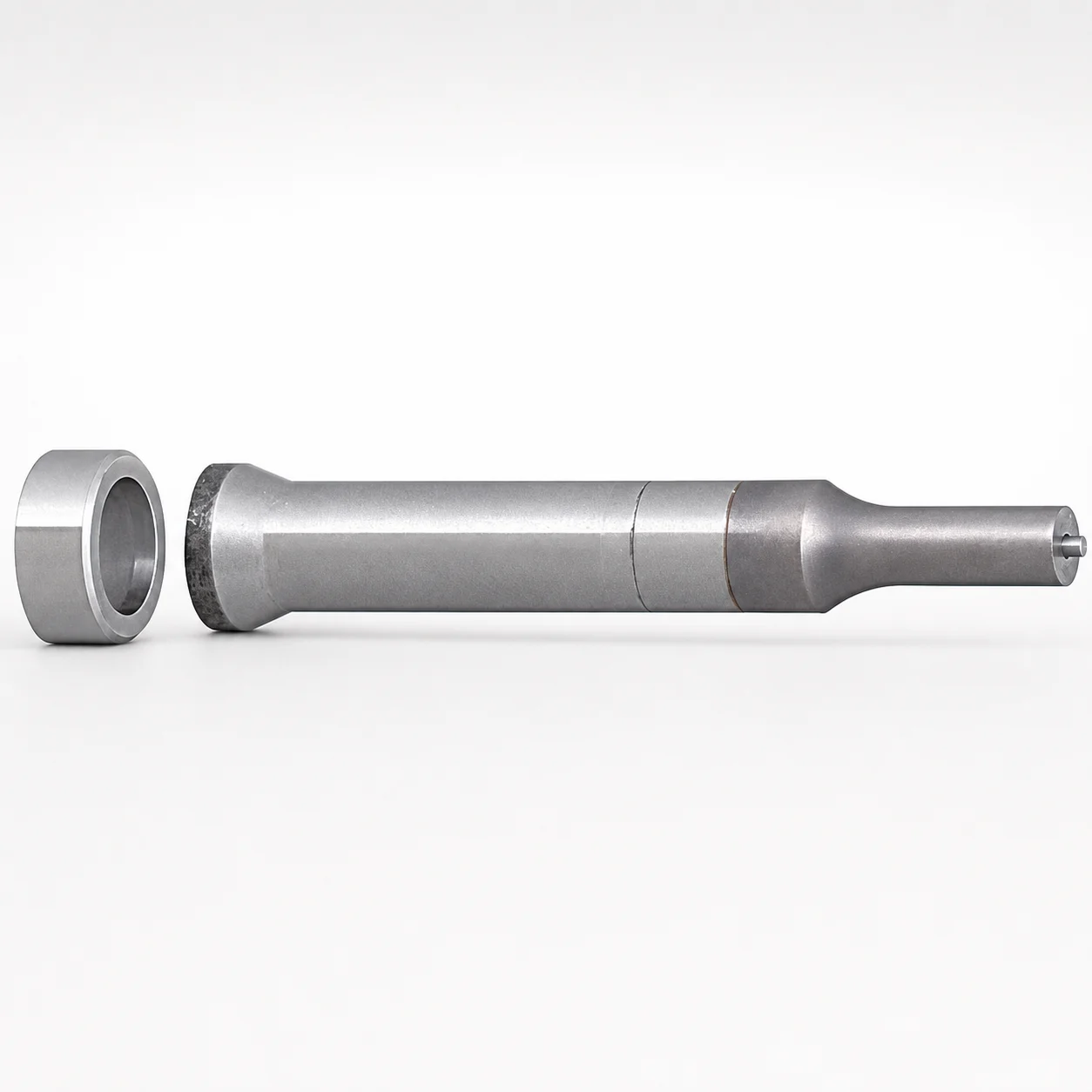
JIS Standard Tapered Head Ejector Punches - HW Coating
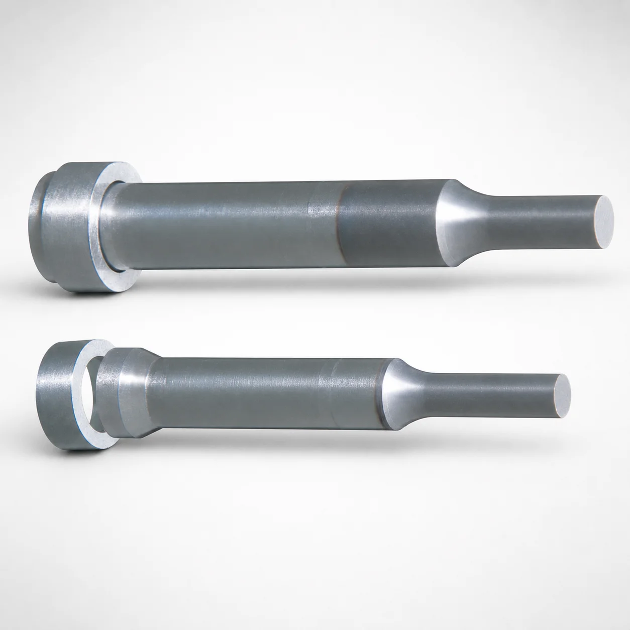
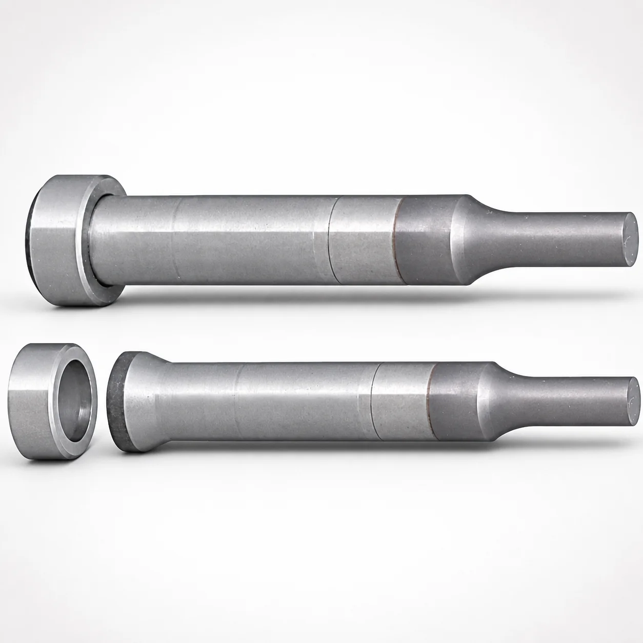
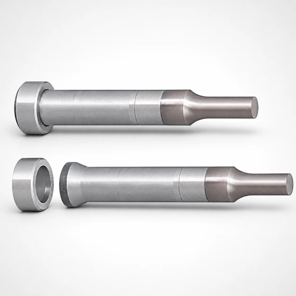
Tapered head ejector punches (HW coated) deliver heavy-load punching for stable mold ejection under production pressure. The tapered head design combined with a single-stepped shank supports consistent positioning and repeatable performance.
- Heavy-load punch geometry with single-stepped shank for secure guidance
- Built-in HW coating improves wear resistance in high-cycle molding
- Standard tip shape (Type A) supports reliable ejector action and alignment
- Suitable for punch-and-eject applications in tool & die manufacturing
Specifications
16 configurations available
| Material | B (Tip length) | D (Shank diameter) (mm) | P (Tip dimension) (mm) | L (L dimension) (mm) | type |
|---|---|---|---|---|---|
| Powdered high-speed steel | L | 8 | 4 ~ 7.99 | 60 ~ 80 | - |
| Powdered high-speed steel | L | 10 | 5 ~ 9.99 | 60 ~ 90 | - |
| Powdered high-speed steel | L | 13 | 6 ~ 12.99 | 70 ~ 100 | - |
| Powdered high-speed steel | L | 16 | 10 ~ 15.99 | 70 ~ 100 | - |
| Powdered high-speed steel | S | 8 | 4 ~ 7.99 | 50 ~ 80 | - |
| Powdered high-speed steel | S | 10 | 5 ~ 9.99 | 55 ~ 90 | - |
| Powdered high-speed steel | S | 13 | 6 ~ 12.99 | 65 ~ 100 | - |
| Powdered high-speed steel | S | 16 | 10 ~ 15.99 | 65 ~ 100 | - |
| SKH51 Equivalent | L | 8 | 4 ~ 7.99 | 60 ~ 80 | - |
| SKH51 Equivalent | L | 10 | 5 ~ 9.99 | 60 ~ 90 | - |
| SKH51 Equivalent | L | 13 | 6 ~ 12.99 | 70 ~ 100 | - |
| SKH51 Equivalent | L | 16 | 10 ~ 15.99 | 70 ~ 100 | - |
| SKH51 Equivalent | S | 8 | 4 ~ 7.99 | 50 ~ 80 | - |
| SKH51 Equivalent | S | 10 | 5 ~ 9.99 | 55 ~ 90 | - |
| SKH51 Equivalent | S | 13 | 6 ~ 12.99 | 65 ~ 100 | - |
| SKH51 Equivalent | S | 16 | 10 ~ 15.99 | 65 ~ 100 | - |
Product Guide
Application Scenarios+
Tapered-head ejector punches with an HW coating are used to transfer ejection force from the ejector plate into the molded part while maintaining stable guidance through the ejector stroke.
In automotive connector and housing molds, the single-stepped shank helps keep the punch aligned during high-cycle operation, reducing side-loading that can cause sticking. The HW coating supports heavy-load punching and improves wear resistance for repeatable ejection.
For consumer electronics and appliance enclosures, these punches match applications where a standard tip geometry (Type A) is preferred for predictable part release and reliable mold timing.
In tool-and-die manufacturing punch-and-eject assemblies, the tapered head and range of shank diameters (8, 10, 13, 16 mm) allow engineers to tune guidance stiffness and punch size to the cavity/core layout.
- Heavy-load punching under production pressure
- Stable positioning via single-stepped shank
- High-cycle wear resistance from HW coating
Material & Process Details+
The punch body is made from powdered high-speed steel with an SKH51 equivalent grade. SKH51 is commonly considered comparable to AISI M2 in performance class, offering a balanced combination of hardness and wear resistance for metal tooling.
For mold ejector punches, this material is typically selected for its ability to withstand repeated sliding/contact with ejector components while maintaining edge integrity under heavy-load ejection cycles.
- Hardness (HRC): The exact hardness value is not specified in the provided data, so confirm with the manufacturer’s heat-treatment record for the specific part.
- Wear resistance vs. toughness: High-speed steel provides strong wear resistance, but peak hardness can reduce toughness compared with more ductile tool steels; proper heat treatment is key.
Heat treatment state: The provided metadata does not specify whether the part is pre-hardened, quenched & tempered, or surface-treated beyond the HW coating. Select the coating/heat-treatment package according to your ejection force, abrasive load, and expected cycle count.
Sizing & Selection Guide+
Select the tapered head ejector punch dimensions by matching the shank diameter (D) and guidance length (L) to the ejector hole and support length in your tool design.
- Shank diameter (D): choose from 8, 10, 13, 16 mm based on the ejector plate bore size and required lateral stiffness.
- Tip length (B): available as L or S (tip-length variant). Use the longer option where additional reach is needed for part release geometry.
- Tip dimension (P): select the range that matches the contact/engagement area; available ranges are 4–7.99, 5–9.99, 6–12.99, and 10–15.99 mm.
- L dimension (length): available ranges include 60–80, 60–90, 70–100, 50–80, 55–90, and 65–100 mm.
To ensure proper fit, maintain the designed clearance/retention in the ejector plate bore for your assembly tolerances, then confirm that the chosen L supports full stroke travel without bottoming. When cavity/core geometry changes, re-evaluate both P (tip engagement) and D (guidance fit) rather than changing only length.
Configurable vs. fixed: Dimension sets are configured by selecting D, P range, B (L/S), and L range from the available options.
Frequently Asked Questions
Which shank diameter (D) options are available for this tapered head ejector punch, and how do I choose between 8, 10, 13, and 16 mm?+
What tip dimension (P) ranges are offered, and how should I match P to the part-release contact area?+
How do I select the length (L) range to avoid bottoming during the ejector stroke?+
What does HW coating add for high-cycle injection molding, and does it change material selection?+
Is the tapered head designed for specific tip geometry, and what is Type A used for?+
Related Products
Need Custom Specifications?
Our engineering team can help with custom configurations, material selection, and volume pricing.