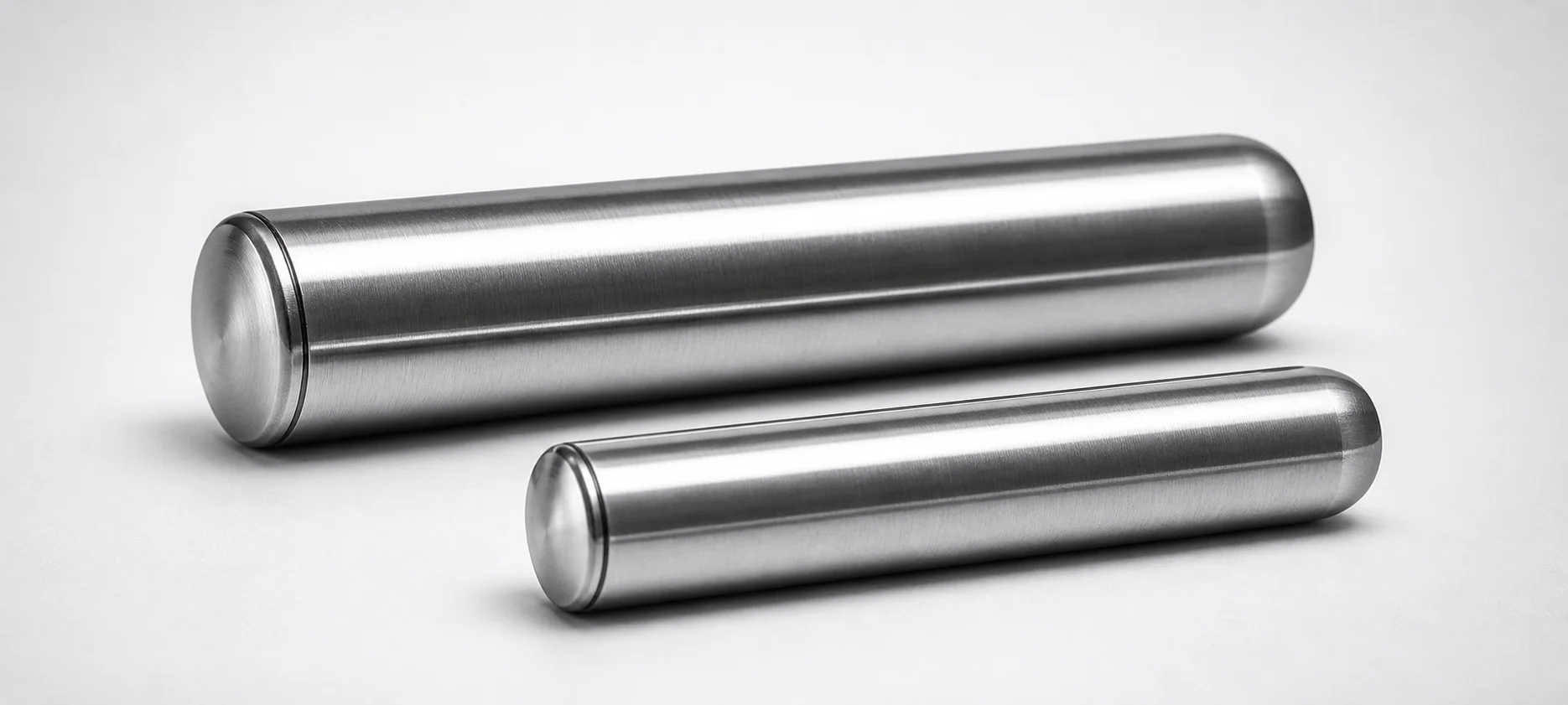
H7 Undersized Tapped Dowel Pins
H7 undersized tapped dowel pins are designed to deliver reliable alignment and positioning in plastic mold and assembly applications. The tapped configuration enables straightforward installation and removal while maintaining consistent component location.
- Undersized h7 tolerance fit supports repeatable mold alignment and stability
- Tapped dowel design allows controlled engagement for efficient assembly/disassembly
- Precision tolerance reference for predictable positioning in production and repair work
- Commonly used in plastic mold tooling for doweling components during cycles
Specifications
24 configurations available
| Shaft Diameter Tolerance | D (Shaft Diameter) (mm) | Length L (mm) | Sale Unit (pieces) | type |
|---|---|---|---|---|
| 0/-0.012 | 5 | 10 | 100 | - |
| 0/-0.012 | 5 | 15 | 100 | - |
| 0/-0.012 | 6 | 10 | 100 | - |
| 0/-0.012 | 6 | 15 | 100 | - |
| 0/-0.012 | 6 | 20 | 100 | - |
| 0/-0.012 | 6 | 25 | 100 | - |
| 0/-0.012 | 6 | 30 | 100 | - |
| 0/-0.015 | 8 | 20 | 100 | - |
| 0/-0.015 | 8 | 30 | 100 | - |
| 0/-0.015 | 8 | 40 | 100 | - |
| 0/-0.015 | 10 | 30 | 100 | - |
| 0/-0.015 | 10 | 40 | 100 | - |
| 0/-0.012 | 5 | 10 | 200 | - |
| 0/-0.012 | 5 | 15 | 200 | - |
| 0/-0.012 | 6 | 10 | 200 | - |
| 0/-0.012 | 6 | 15 | 200 | - |
| 0/-0.012 | 6 | 20 | 200 | - |
| 0/-0.012 | 6 | 25 | 200 | - |
| 0/-0.012 | 6 | 30 | 200 | - |
| 0/-0.015 | 8 | 20 | 200 | - |
| 0/-0.015 | 8 | 30 | 200 | - |
| 0/-0.015 | 8 | 40 | 200 | - |
| 0/-0.015 | 10 | 30 | 200 | - |
| 0/-0.015 | 10 | 40 | 200 | - |
Product Guide
Application Scenarios+
These H7 undersized tapped dowel pins are used to establish repeatable alignment between mold components, such as plates, cores, and cavities, during plastic injection molding tooling builds. The undersized shaft-to-hole fit (H7 tolerance) helps maintain stable positioning across production cycles while supporting controlled assembly.
- Automotive connector and housing molds: tapped dowel pins simplify alignment of multiple parting-line components, reducing the risk of drift during high-cycle setups. Their tapped configuration supports efficient installation and removal for maintenance.
- Consumer product injection molds: use them to dowel-register interchangeable inserts or wear components. The consistent positional reference improves repeatability when inserts are swapped for different SKUs or cavity configurations.
- Mold assembly/repair workflows: when tooling must be disassembled for inspection, reassembly is faster due to the threaded engagement, while the H7 undersized tolerance supports predictable location.
Material & Process Details+
The provided specifications for this series focus on tolerance, dimensions, and tapped geometry; no steel grade, heat-treatment state, or hardness value is included in the input data. As a result, material properties such as HRC hardness, wear resistance, and toughness trade-offs cannot be stated reliably for this exact variant.
When selecting a material for dowel pins in plastic mold tooling, engineers typically match the pin hardness to the expected wear and handling requirements (frequent assembly/disassembly favors higher wear resistance). The most common choices are tool steels with controlled through-hardening and/or surface strengthening, but the heat treatment type (e.g., quenched & tempered, nitriding) must be confirmed for the specific order configuration.
- Data gap: steel grade and heat treatment are not specified in the supplied parameters.
- Recommendation: verify the supplier’s material/heat-treatment certificate for the final part number before locking in design assumptions.
Sizing & Selection Guide+
To select the correct tapped dowel pin size, match the pin shaft diameter D and length L to your mold cavity/core or locating hole requirements. This series is available with D = 5, 6, 8, 10 mm and L = 10, 15, 20, 25, 30, 40 mm.
- Choose diameter by function: select the corresponding D that aligns with your dowel-hole diameter, then rely on the H7 undersized fit to ensure repeatable positioning.
- Choose length for engagement: pick L to achieve adequate thread engagement and safe insertion depth without bottoming in the mating component.
- Tolerance/fit consideration: the shaft diameter tolerance is given as 0/-0.012 or 0/-0.015, meaning the shaft is permitted to be below nominal. Confirm which tolerance option is required for your hole size and desired clearance.
Dimensions are fixed by the listed D and L options; tolerance behavior is the configurable element via the provided shaft tolerance range.
Frequently Asked Questions
What does “H7 undersized” mean for locating accuracy in plastic injection mold assemblies?+
For this series, the dowel pin is specified as H7 undersized, using an undersized shaft-to-hole fit concept to support stable, repeatable alignment. The shaft diameter tolerance is provided as 0/-0.012 or 0/-0.015, which directly affects clearance and positional repeatability.
To finalize fit, match the pin’s selected tolerance option to your locating hole size and the engagement depth needed for reliable registration.
Which shaft diameter (D) options are available for this tapped dowel pin series?+
This series offers D (shaft diameter) in 5, 6, 8, and 10 mm. Selecting the correct D is the primary step in matching your mold’s dowel hole diameter for alignment.
After choosing D, confirm the applicable shaft tolerance range (0/-0.012 or 0/-0.015) to ensure the intended fit.
How do I choose the correct dowel pin length L for tapped engagement?+
Available lengths are L = 10, 15, 20, 25, 30, and 40 mm. Choose L to provide sufficient thread engagement during assembly while preventing bottoming in the receiving component.
For multi-plate mold tooling, verify that the insertion depth accounts for the mating thicknesses plus any functional clearances required by your alignment strategy.
Are there multiple tolerance variants for the shaft diameter, and how do they affect clearance?+
Yes. The input data specifies two shaft diameter tolerance options: 0/-0.012 and 0/-0.015. Because the tolerance is undersized (negative deviation from nominal), the actual shaft can be smaller, increasing clearance relative to a tight fit.
Select the variant that best matches your hole tolerance and the alignment stability you need over repeated assembly cycles.
What is the correct selection between D and L ranges when designing for maintenance/part replacement?+
When planning for insert replacement or repair cycles, prioritize consistent positional reference by selecting the exact D (5/6/8/10 mm) for your locating hole and the correct L (10–40 mm) for the required engagement depth.
The tapped design supports efficient installation and removal, while the H7 undersized fit supports predictable alignment when components are reassembled.
Related Products
Need Custom Specifications?
Our engineering team can help with custom configurations, material selection, and volume pricing.