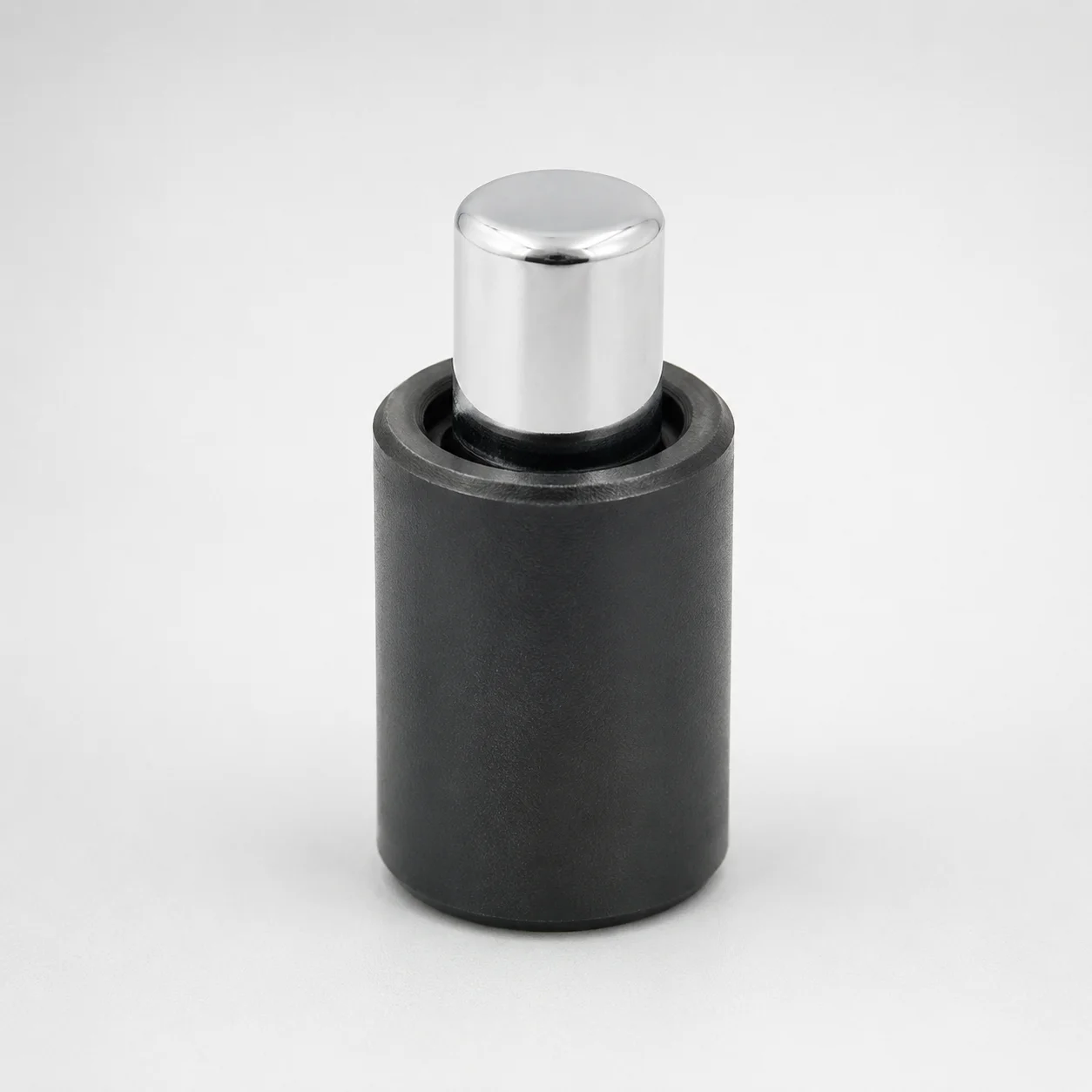
Gas Springs for Plastic Molds
Gas Springs for Plastic Molds provide consistent assisting force for mold and tooling mechanisms, helping stabilize motion throughout production. Select stroke and load range options to match your press and linkage requirements.
- Configurable maximum load supports different closing and return force needs
- Multiple initial load options for controlled starting force at setup
- Available stroke lengths from 100 to 250 mm for fit-to-application design
- Designed for plastic mold assist applications where smooth movement improves cycle consistency
Specifications
26 configurations available
| Maximum Load (N[kgf]) | Initial Load (N[kgf]) | S (Stroke) (mm) | D (Gas Spring Diameter) (mm) | L (Gas Spring Holder Full Length) (mm) | type |
|---|---|---|---|---|---|
| 3166(322) | 2000[204] | 100 | 38 | 250 | - |
| 3191(327) | 2000[204] | 125 | 38 | 300 | - |
| 3213(327) | 2000[204] | 160 | 38 | 370 | - |
| 3329(329) | 2000[204] | 200 | 38 | 450 | - |
| 7217(735) | 4500[459] | 100 | 45 | 285 | - |
| 7299(744) | 4500[459] | 125 | 45 | 335 | - |
| 7375(752) | 4500[459] | 160 | 45 | 405 | - |
| 7431(757) | 4500[459] | 200 | 45 | 485 | - |
| 9195(937) | 5500[561] | 100 | 50 | 295 | - |
| 9362(954) | 5500[561] | 125 | 50 | 345 | - |
| 9520(970) | 5500[561] | 160 | 50 | 415 | - |
| 9642(983) | 5500[561] | 200 | 50 | 495 | - |
| 9744(993) | 5500[561] | 250 | 50 | 595 | - |
| 3958(403) | 2500[255] | 100 | 38 | 250 | - |
| 3988(406) | 2500[255] | 125 | 38 | 300 | - |
| 4016(409) | 2500[255] | 160 | 38 | 370 | - |
| 4036(411) | 2500[255] | 200 | 38 | 450 | - |
| 8015(817) | 5000[510] | 100 | 45 | 285 | - |
| 8106(826) | 5000[510] | 125 | 45 | 335 | - |
| 8191(835) | 5000[510] | 160 | 45 | 405 | - |
| 8254(841) | 5000[510] | 200 | 45 | 485 | - |
| 10845(1105) | 6500[663] | 100 | 50 | 295 | - |
| 11042(1125) | 6500[663] | 125 | 50 | 345 | - |
| 11229(1145) | 6500[663] | 160 | 50 | 415 | - |
| 11372(1159) | 6500[663] | 200 | 50 | 495 | - |
| 11493(1171) | 6500[663] | 250 | 50 | 595 | - |
Product Guide
Application Scenarios+
Gas-assisted components are used inside injection mold tooling to maintain stable movement for complex actuation points, especially where consistent closing/return behavior is critical to cycle time. This variant is suited for repeatable assist-force in plastic mold mechanisms that experience frequent motion reversals.
- Automotive connector and housing molds: Install gas springs in ejector/return linkages to smooth the force profile during open-close actions, helping reduce operator effort and improve cycle consistency under high repetition.
- Consumer product housings: Use the available stroke (S = 100–250 mm) and selectable maximum load (3166–11493 N) to match the travel of hinged lids or multi-part core pulls, improving repeatability during full production.
- Packaging and appliance components: Select a specific initial load option to control the starting force during setup, which supports stable motion at low-displacement stages.
Material & Process Details+
For this gas spring accessory set, the functional performance is governed primarily by the compressed gas charge and sealing system rather than a conventional tool steel heat-treatment route. As such, hardness (HRC) is not specified in the provided data because the energy storage element is not a quenched-and-tempered steel cutting insert or die block.
Key engineering considerations typically focus on:
- Load stability vs. stroke: selecting the correct maximum load (3166–11493 N) and stroke (S = 100–250 mm) to achieve the desired assist-force curve.
- Initial load selection: choosing from the listed initial load values to control the early-stage force output at setup.
- Fit to linkage: matching external diameter D (38/45/50 mm) and holder length L (250–595 mm) to avoid binding and ensure smooth movement.
If you require material grade or a hardness guarantee for the rod/sealing surfaces, confirm with the supplier documentation for this MISUMI series.
Sizing & Selection Guide+
Select dimensions by matching your mold mechanism travel and force needs, then verify clearance and mounting length. Start with the required assist behavior: choose stroke S from 100, 125, 160, 200, 250 mm so the gas spring travel matches the linkage’s active stroke.
- Force selection: pick the maximum load in the range 3166–11493 N (kgf equivalents not required for selection if your force model uses N). Then select an initial load from the listed options (e.g., 2000, 2500, 4500, 5000, 5500, 6500 N variants).
- Mounting interface: choose the gas spring diameter D = 38, 45, or 50 mm to fit the available bracket space without interference.
- Overall packaging length: set the holder full length L = 250–595 mm to fit within the mold base and maintain the correct pre-assembled position.
All listed dimensions are configuration-fixed per variant; tolerance/fit values are not provided in the input data, so confirm mechanical drawings for clearance critical interfaces.
Frequently Asked Questions
How do I choose the correct stroke (S) for a plastic mold assist mechanism?+
What’s the difference between maximum load and initial load for gas springs used in mold tooling?+
Which gas spring diameter (D) should I select for available mounting space in the mold?+
How does holder full length (L) affect installation and pre-load position?+
Can I use this gas spring series across different mold mechanisms with the same stroke but different force demands?+
Need Custom Specifications?
Our engineering team can help with custom configurations, material selection, and volume pricing.