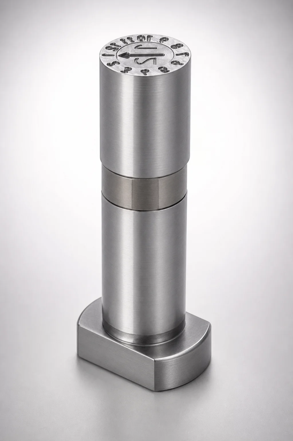
26-Year Adjustable Length Date Mark Pin Sets
26-year adjustable length date mark pin sets provide a compact, core-ready system for mold date coding. The concave character style and modular arrow-and-ring components help maintain clear marking through production cycles.
- Concave character design with core pin mounting for repeatable alignment
- Modular marking system: inside arrow and outside ring
- Adjustable length configuration supports flexible engraving positions
- Engraving designation by WOS for consistent date-mark readability in molds
Specifications
42 configurations available
| D (Outer diameter) (mm) | Year (year) | Engraving character designation | LB (L dimension) (mm) | type |
|---|---|---|---|---|
| 6 | - | - | 10 ~ 50 | - |
| 8 | - | - | 10 ~ 60 | - |
| 10 | - | - | 10 ~ 70 | - |
| 6 | 26 | - | - | - |
| 8 | 26 | - | - | - |
| 10 | 26 | - | - | - |
| 6 | - | - | - | - |
| 8 | - | - | - | - |
| 10 | - | - | - | - |
| 6 | - | - | - | - |
| 8 | - | - | - | - |
| 10 | - | - | - | - |
| 6 | - | - | - | - |
| 8 | - | - | - | - |
| 10 | - | - | - | - |
| 6 | - | ※Designation by WOS | - | - |
| 8 | - | ※Designation by WOS | - | - |
| 10 | - | ※Designation by WOS | - | - |
| 6 | - | ※Designation by WOS | - | - |
| 8 | - | ※Designation by WOS | - | - |
| 10 | - | ※Designation by WOS | - | - |
| 6 | - | ※Designation by WOS | - | - |
| 8 | - | ※Designation by WOS | - | - |
| 10 | - | ※Designation by WOS | - | - |
| 6 | - | ※Designation by WOS | - | - |
| 8 | - | ※Designation by WOS | - | - |
| 10 | - | ※Designation by WOS | - | - |
| 6 | - | ※Designation by WOS | - | - |
| 8 | - | ※Designation by WOS | - | - |
| 10 | - | ※Designation by WOS | - | - |
| 6 | - | ※Designation by WOS | - | - |
| 8 | - | ※Designation by WOS | - | - |
| 10 | - | ※Designation by WOS | - | - |
| 6 | - | ※Designation by WOS | - | - |
| 8 | - | ※Designation by WOS | - | - |
| 10 | - | ※Designation by WOS | - | - |
| 6 | - | ※Designation by WOS | - | - |
| 8 | - | ※Designation by WOS | - | - |
| 10 | - | ※Designation by WOS | - | - |
| 6 | - | ※Designation by WOS | - | - |
| 8 | - | ※Designation by WOS | - | - |
| 10 | - | ※Designation by WOS | - | - |
Product Guide
Application Scenarios+
These adjustable length date mark pin sets are used in injection mold tooling where durable, repeatable cavity identification is required across long production runs. The system is well-suited for date/coding molds for consumer packaging and household goods, because the concave character geometry combined with modular arrow-and-ring components helps keep markings readable after multiple cycles.
In automotive and appliance component molding, designers can set the engraving position by selecting the appropriate adjustable length range, supporting alignment with core/pin mounting features and maintaining consistent visible contrast on molded parts. For multi-cavity molds that require standardized date placement, the inside arrow and outside ring module concept supports repeatable character formation while keeping assembly compact.
- Adjustable length (LB): fine-tunes engraving depth/placement within the core layout.
- Concave character style: promotes stable marking legibility under typical surface deformation.
- WOS designation: supports consistent character set selection for tooling standards.
Material & Process Details+
The provided product data focuses on the character geometry (concave date marking) and the adjustable dimensions (D and LB). No steel grade, hardness (HRC), heat treatment state (e.g., quenched & tempered, nitrided), or wear/toughness values are specified for this specific MISUMI set, so those material properties cannot be verified from the input.
For engineering fit-in to existing mold standards, confirm the supplier’s available material options for date-mark insert pins in your program documentation, especially if you are comparing to hardened tool steels commonly used for character engraving. When material choices differ, the trade-off typically affects wear resistance vs. toughness: harder conditions improve abrasion resistance of engraved features, while tempered/tougher conditions can reduce chipping risk during insertion, extraction, or repeated thermal cycling.
- Data available: D (6/8/10 mm), Year (26), WOS designation.
- Data missing in this dataset: steel grade, HRC, and heat treatment.
Sizing & Selection Guide+
Select the pin set size by matching the outer diameter D and adjustable length LB to your core mounting and engraving position requirements. The available D values are 6, 8, or 10 mm, and the available LB ranges are 10–50 mm, 10–60 mm, or 10–70 mm.
- Step 1 (Core interface): choose D to match your core pin mounting pocket/spec so the insert-to-core fit supports stable alignment.
- Step 2 (Engraving placement): set LB within the correct range to position the date characters at the desired surface height on the molded part.
- Step 3 (Character standard): confirm the engraving character designation is ※Designation by WOS and the fixed year is 26, ensuring your character set aligns with internal tooling documents.
Tolerance/fit requirements are not provided in the dataset; therefore, verify the allowable mounting clearances and any positional tolerances from your mold base/core drawing package before final selection.
Frequently Asked Questions
What outer diameter options (D) are available for this adjustable length date mark pin set?+
What adjustable length ranges (LB) can I choose for positioning the 26-year date characters?+
Is the year marking fixed to 26, or can it be changed in this set?+
What does “※Designation by WOS” mean for selecting the correct engraving character layout?+
How do I match the pin set dimensions to my multi-cavity core so the date marks register correctly?+
Related Products
Need Custom Specifications?
Our engineering team can help with custom configurations, material selection, and volume pricing.