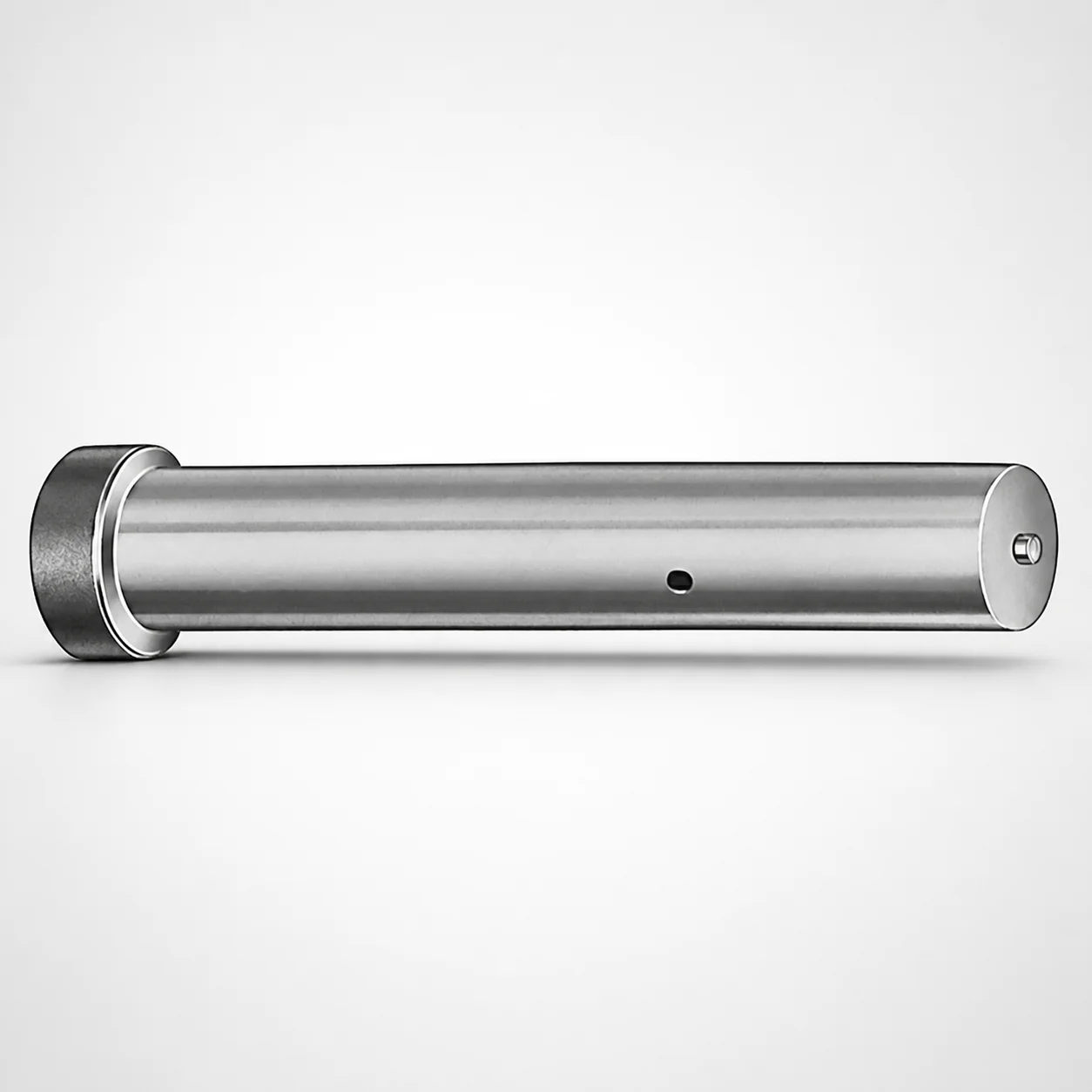
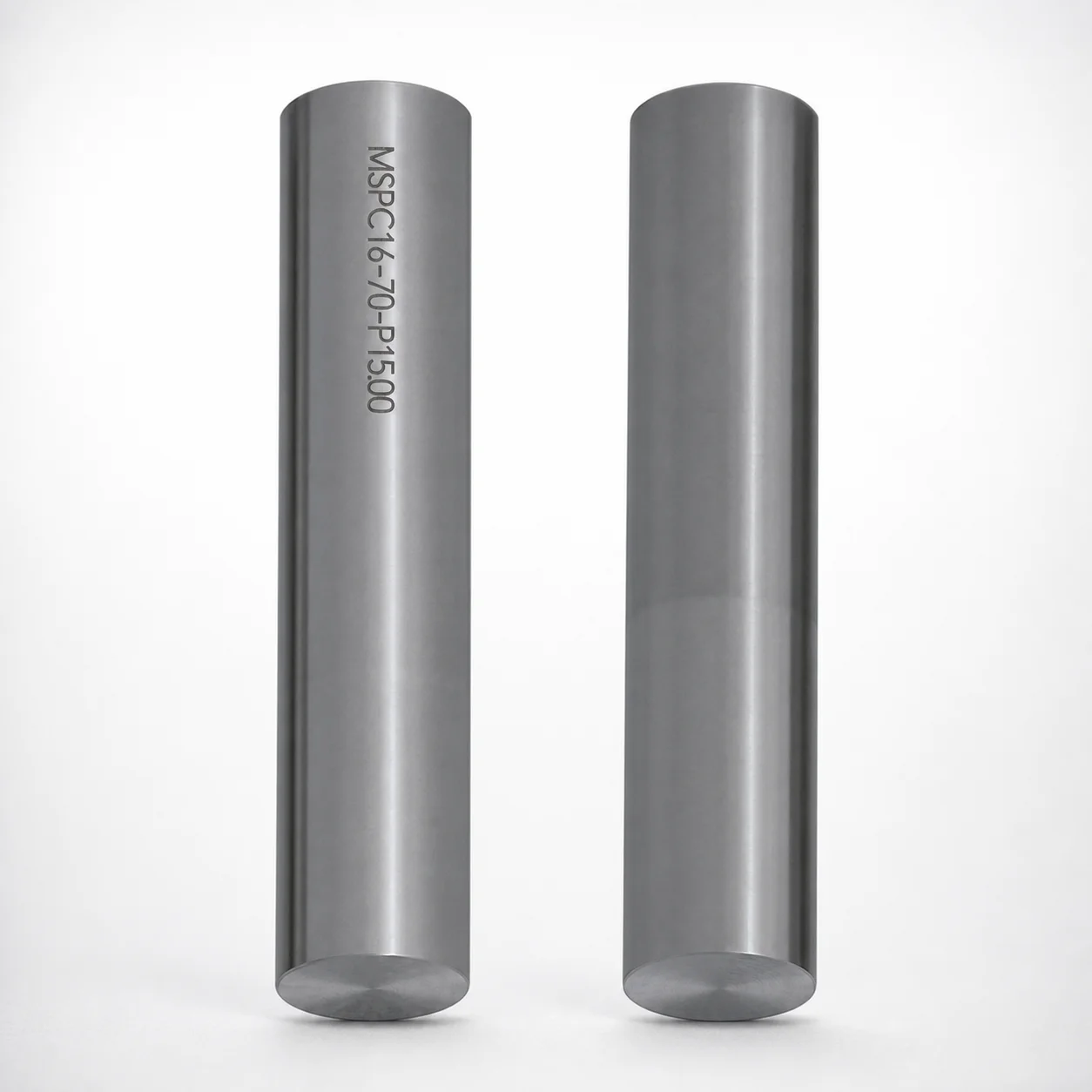
Metric Straight Ejector Punches with CRN Coating
Metric straight ejector punches (CRN coated) from Dayton Lamina provide reliable ejection performance in tooling applications where wear resistance and stable fit matter. Designed for repeatable press cycles with consistent punch function.
- Straight punch geometry supports stable, aligned ejection in dies
- CRN coating enhances wear resistance for demanding production
- Metric selection supports L length ranges for tooling fit
- Suitable for stamping and die applications requiring dependable ejector action
Specifications
1 configurations available
| L (Length) (mm) | P Dimension (mm) |
|---|---|
| 50 ~ 90 | 5 ~ 16 |
Product Guide
Application Scenarios+
Metric straight ejector punches with CRN coating are used in injection molding and die tooling where the ejector system must push parts out repeatedly with minimal wear and consistent alignment.
- Die casting ejector tooling: In die casting molds, these punches support stable, straight-line ejection so the ejector force stays aligned. The CRN coating helps maintain surface integrity under high-contact cycles.
- Stamping and progressive die sets: For stamping applications, straight punch geometry contributes to predictable ejection and reduced risk of sticking. The durable wear surface is suited for long runs where sleeve/punch clearance stability matters.
- Mixed-material inserts and short-stroke ejection: When tooling design calls for metric length selection (L) to match the ejector travel and part thickness, this variant supports repeatable press cycles with consistent punch function.
Overall, the straight geometry plus CRN wear layer makes it well-suited for production environments that demand both ejection stability and resistance to abrasion.
Material & Process Details+
The provided data specifies a CRN (chromium nitride) coating on a metric straight ejector punch. CRN coatings are commonly selected for their high hardness and improved wear resistance, helping reduce abrasion and maintain a stable contact surface over extended press or die casting cycles.
Because no specific steel grade, core hardness (HRC), or heat-treatment condition (e.g., quench & temper or nitriding) is listed in the input data, those properties should be confirmed with the supplier before final design sign-off.
- Wear vs. toughness trade-off: Hard wear coatings like CRN improve surface durability but typically do not replace the need for a sufficiently tough substrate core to prevent chipping under off-axis loads.
- Manufacturing process: Typical manufacturing involves machining the straight punch body to metric dimensions, followed by coating application of the CRN layer for the functional wear zone.
For projects comparing variants, the key differentiators are coating system performance and the substrate’s hardness/toughness match to your ejection loads.
Sizing & Selection Guide+
Use the fixed dimensions to match the punch to your ejector layout and part ejection requirements. This series is specified with L (Length) = 50–90 mm and P = 5–16 mm.
- Choose L first: Select the punch length within 50–90 mm so the working end provides the required ejection travel without bottoming in the guide or exceeding allowable stroke.
- Match P to the fit requirement: Dimension P (5–16 mm) must correspond to the punch’s intended working diameter/size used in your ejector bushing or guide arrangement.
- Allow for clearance: Because tolerances for the punch diameter and mating guide/sleeve are not provided, confirm the clearance and fit strategy with your standard ejector/bushing specs to prevent binding or excessive play.
- Metric tooling compatibility: Since these are metric straight punches, ensure your die standard parts and drawings use compatible metric dimensions for both the punch seat and guide components.
Once L and P are selected, verify alignment assumptions for straight geometry to maintain consistent ejection force.
Frequently Asked Questions
Which ejector die applications benefit most from the CRN-coated straight punch geometry?+
This variant is intended for tooling where wear resistance and stable ejection alignment are critical, such as die casting ejector systems and stamping die sets with repeatable press cycles.
The straight punch geometry supports aligned ejection, while the CRN coating is specified to enhance wear resistance for demanding production use.
How do I select the correct punch length (L) for ejector travel?+
Pick a value of L within 50–90 mm to match your required ejection travel and the stroke limits of the ejector mechanism.
Confirm that the punch working end will not bottom in the guide/bushing and that the length provides consistent contact through the cycle. Tolerance and clearance values are not specified, so validate against your ejector system design standards.
What does the P dimension (5–16 mm) control for fit with ejector guides or bushings?+
P = 5–16 mm is the fixed size parameter provided for this series and should be matched to the mating guide/sleeve or design interface used in your die.
Because the input data does not provide tolerance grades, ensure the clearance/fit matches your standard for punch-to-bushing engagement to avoid sticking or excessive lateral play.
Do I need to confirm the substrate steel grade and hardness (HRC) before finalizing the mold design?+
Yes. The input data confirms the CRN coating but does not list the underlying steel grade, heat treatment state, or core hardness (HRC).
For load-bearing and abrasion-heavy cycles, verify that the substrate hardness/toughness is appropriate for your ejection forces and any side-loading expected during operation.
Is this series intended for long-run production cycles in die casting and stamping?+
The meta description specifically positions these CRN-coated metric straight ejector punches for long service in die casting and stamping.
In design terms, you should size L (50–90 mm) and P (5–16 mm) to maintain consistent ejection alignment and stable fit, since stable geometry plus the wear layer is the functional intent.
Related Products
Need Custom Specifications?
Our engineering team can help with custom configurations, material selection, and volume pricing.