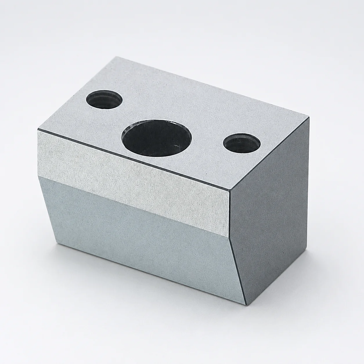
O1 Tool Steel Locking Blocks with Angular Pin Holes - Inlay Type
O1 Tool Steel locking blocks with angular pin holes (inlay type) provide a compact method for locating and securing components using an angular hole insert. Plate side fixing with tapped bolt mounting improves repeatable positioning in assembly and tooling.
- Integrated angular hole for reliable inlay retention and alignment
- O1 tool steel construction supports wear resistance in working environments
- Inlay-type design enables controlled inlay part dimension selection
- Used with tooling plates where plate-side fixing is required
Specifications
4 configurations available
| Block Height T (mm) | A/W (Block width) (mm) | H/E (Inlay Part Dimension) (mm) | D (Angular Hole Diameter) (mm) | A (Angle) (°) | G (Angle) (°) | type |
|---|---|---|---|---|---|---|
| 20 ~ 30 | 38 ~ 58 | 10 ~ 20 | 6 | 10 ~ 20 | 12 ~ 25 | - |
| 20 ~ 30 | 38 ~ 58 | 10 ~ 20 | 8 | 10 ~ 20 | 12 ~ 25 | - |
| 30 ~ 50 | 38 ~ 68 | 10 ~ 40 | 10 | 10 ~ 20 | 12 ~ 25 | - |
| 35 ~ 60 | 48 ~ 78 | 10 ~ 50 | 13 | 10 ~ 20 | 12 ~ 25 | - |
Product Guide
Application Scenarios+
This inlay-type locking block is used in injection mold tooling to position and retain components inside undercut/undercut-plate systems where repeatable location is required. Its angular pin hole design accepts an inlay feature to create stable, controlled retention during part opening and closing cycles.
Common scenarios include automotive connector and terminal molds, where slide or insert assemblies must return to the same alignment after thermal cycling. The block’s compact geometry and plate-side tapped bolt fixing help maintain repeatable placement in multi-cavity tooling.
It’s also well suited for appliance and consumer product housings that use modular tooling plates for quick changeovers. The inlay approach lets engineers select the inlay part dimension (H/E) to fine-tune fit and engagement.
In all cases, the angular feature angles (A = 10–20° and G = 12–25°) support consistent mechanical guidance, improving alignment compared with straight-through locating methods.
Material & Process Details+
O1 tool steel is selected for these locking blocks due to its balanced wear resistance and toughness for tooling components that experience frequent sliding/contact. O1 is commonly used in tooling applications where impact resistance is needed alongside moderate abrasion resistance.
Material processing typically involves machining to size, followed by heat treatment to reach a working hardness suitable for precision locating surfaces. For mold component use, blocks are usually oil quenched and tempered to achieve target hardness in the ~58–62 HRC range, depending on the final tempering condition. Higher hardness improves wear resistance but can reduce toughness if over-tempered or too aggressively quenched.
- After hardening/tempering, dimensional stability is critical for maintaining engagement through the angular pin hole.
- If compared to more wear-focused grades (e.g., higher-alloy D-series/H-series steels), O1 offers a practical toughness–wear compromise for repeatable retention in modular plates.
Sizing & Selection Guide+
Selection starts with the block’s height T and width A/W so the locking block fits the available plate pocket and maintains proper alignment with the mating inlay. Choose T from 20–30 mm, 30–50 mm, or 35–60 mm and select A/W from 38–58 mm, 38–68 mm, or 48–78 mm based on your plate-side space and load path.
Next, match the inlay part dimension H/E to the required engagement depth range: 10–20 mm, 10–40 mm, or 10–50 mm. This controls retention geometry and helps achieve consistent mechanical positioning.
- Pick the angular hole diameter D (6, 8, 10, or 13 mm) to match the mating inlay pin/insertion hardware.
- Confirm angular alignment using A = 10–20° and G = 12–25° against your tooling system angles.
- Tolerance/fit: ensure clearance and interference are defined by your inlay design; the hole diameter D drives the fundamental clearance/gap for reliable assembly.
All listed dimensions are configurable within the given ranges; use your cavity/core requirements to constrain the allowable package envelope on the plate.
Frequently Asked Questions
How do I select the correct angular hole diameter D for an inlay retention design?+
Choose D from 6, 8, 10, or 13 mm to match the mating inlay feature that passes through or engages the angular hole. The selected D defines the primary fit condition, so your clearance/interference should be established by the inlay part diameter and your assembly tolerance stack.
After selecting D, verify that the angular geometry remains compatible with your fixed angles (A = 10–20°, G = 12–25°) to avoid binding during mold open/close cycles.
Which combinations of T (block height) and A/W (block width) best fit typical undercuts/plates packaging?+
Use T ranges of 20–30 mm, 30–50 mm, or 35–60 mm based on the available vertical pocket depth in your plate. Then select A/W from 38–58 mm, 38–68 mm, or 48–78 mm to ensure full coverage and sufficient wall thickness around the bolt fixing region.
For modular plate systems, always confirm there is enough clearance for plate-side tapped bolt mounting so alignment is repeatable after disassembly.
What is the role of H/E (inlay part dimension) when using this locking block as an inlay type?+
H/E controls the inlay engagement depth and therefore the retention behavior. Select from 10–20 mm, 10–40 mm, or 10–50 mm to match the required mechanical hold while accommodating wear allowance on the inlay surface.
Because the inlay geometry is what truly sets engagement, H/E selection should be coordinated with D and the angular angles (A and G) to maintain proper alignment.
Are the angles A and G fixed, and how do they affect alignment?+
Angle A is specified as 10–20° and angle G as 12–25°. They are not single-point values; you must choose the configuration that matches your tooling system’s mating wedge or inlay profile.
Incorrect angle selection can cause reduced engagement, uneven load transfer, or binding during operation, especially in high-cycle connector and insert tooling.
Why is O1 tool steel commonly chosen for locking blocks in plate-side fixed tooling?+
O1 tool steel provides a practical balance of wear resistance and toughness for locating components that experience frequent contact. In mold tooling, blocks are typically machined and then oil quenched and tempered to reach a target hardness around ~58–62 HRC.
This hardness level helps resist wear at the angular engagement surfaces while maintaining enough toughness to tolerate assembly stresses from plate-side mounting.
Related Products
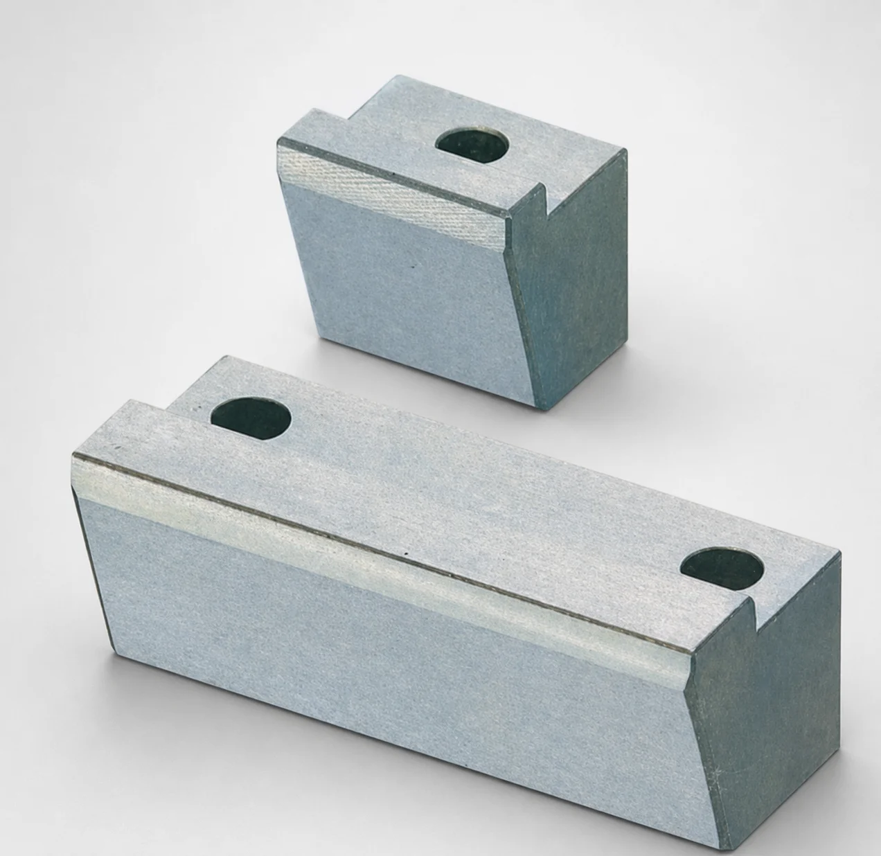
O1 Tool Steel Positioning Locking Blocks with Oil Grooves
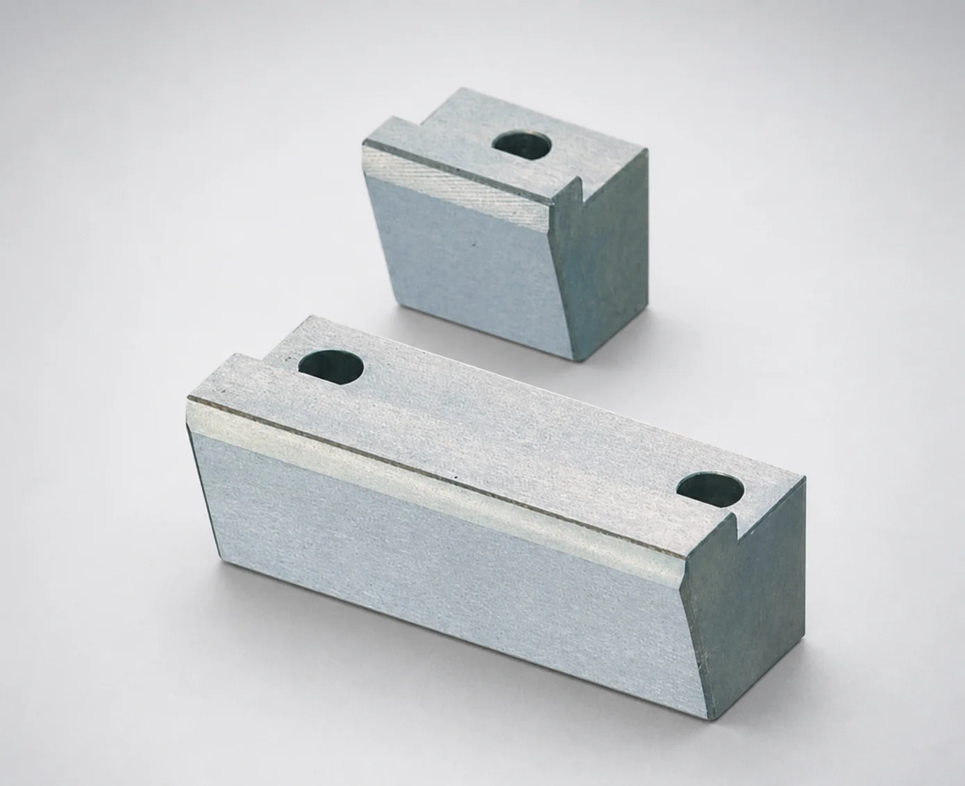
Positioning Locking Blocks Angle Configurable, Oil-Free Options
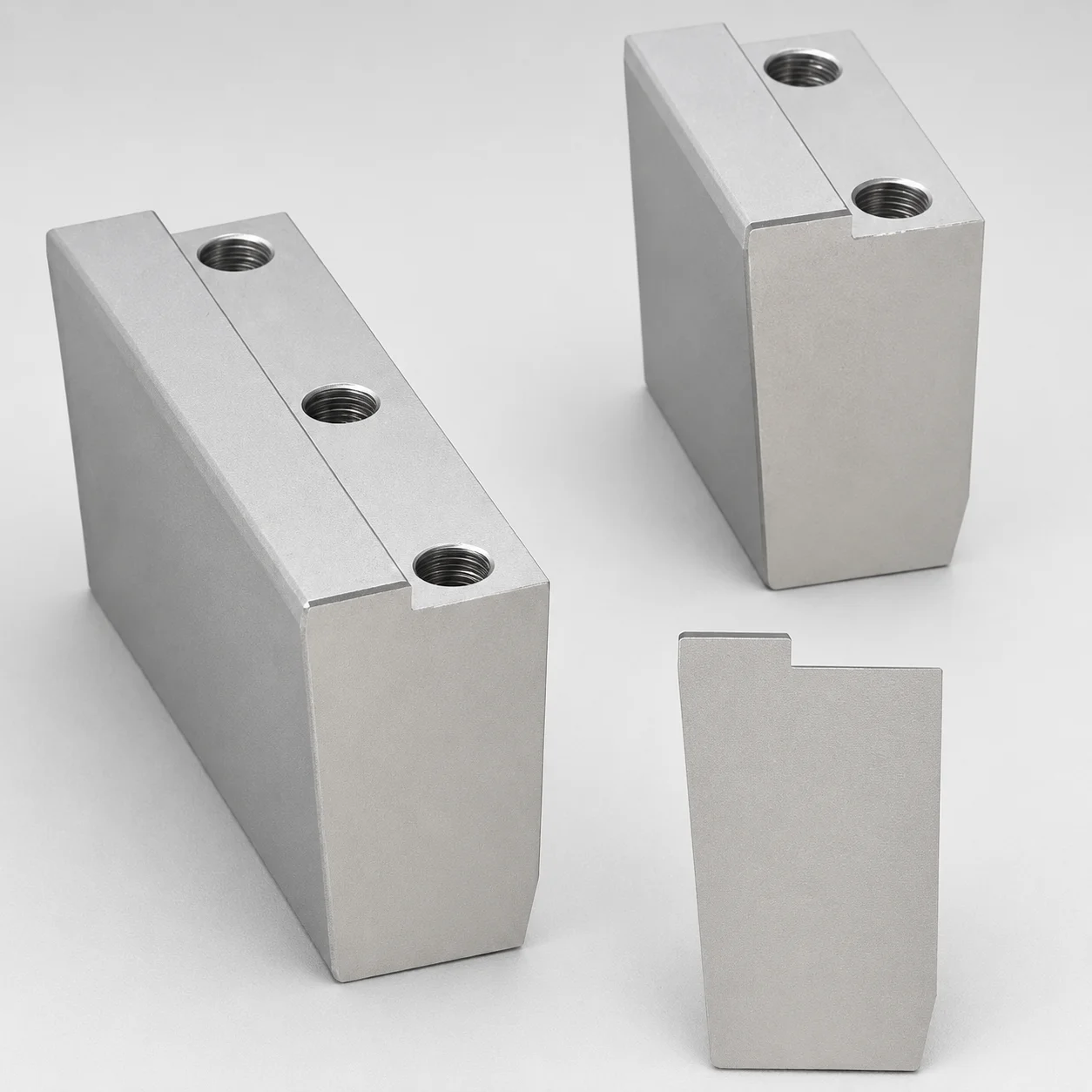
O1 Tool Steel Positioning Locking Blocks - Beveled Edge Bottom (KN)
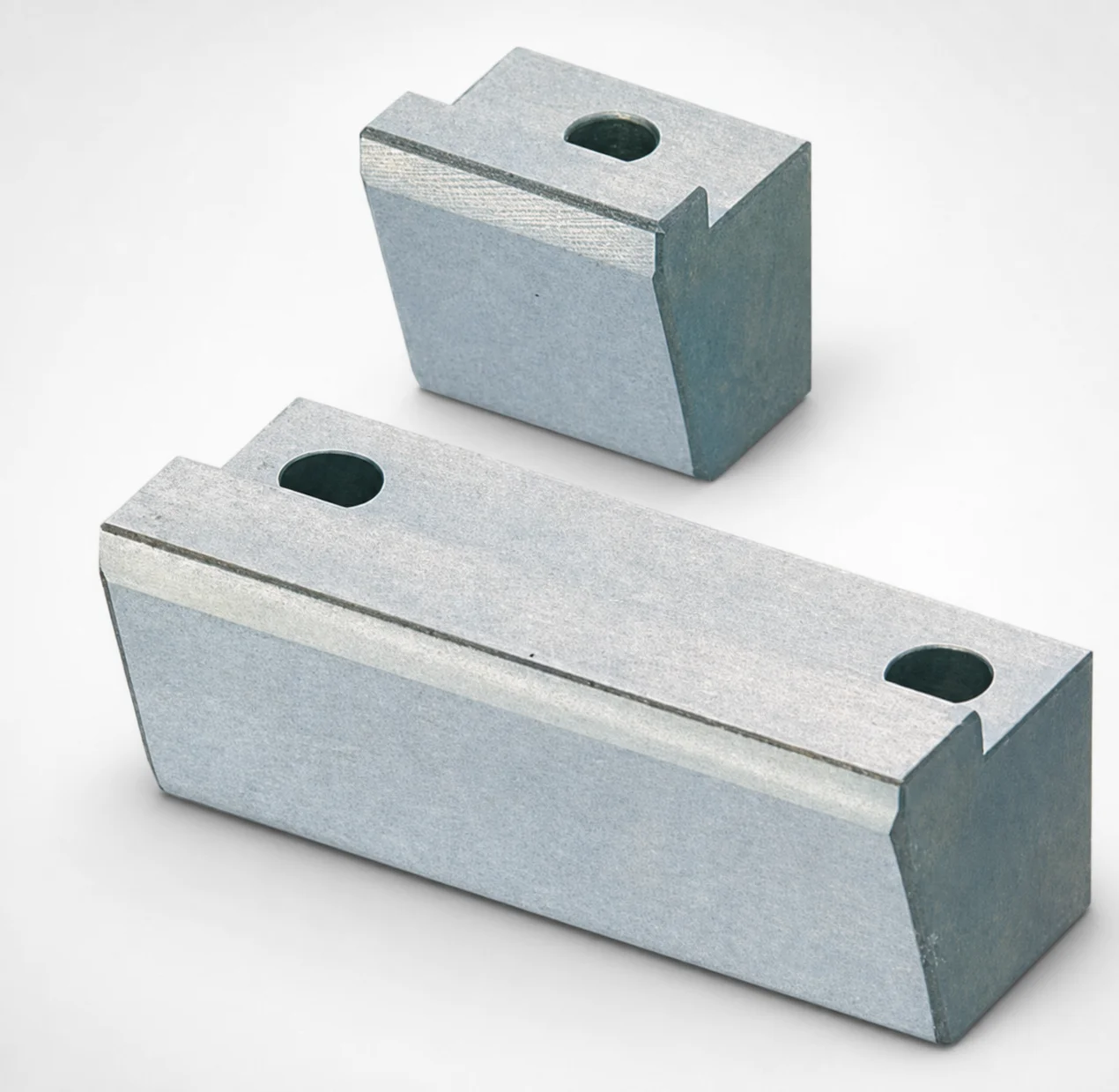
O1 Tool Steel Positioning Locking Blocks - Angle Configurable
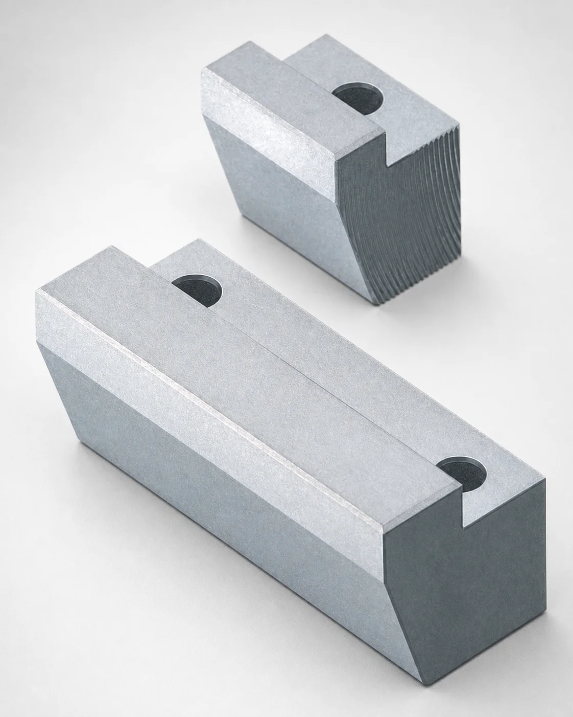
Locking Blocks - Fixed Angle & Inlay Height Configurable
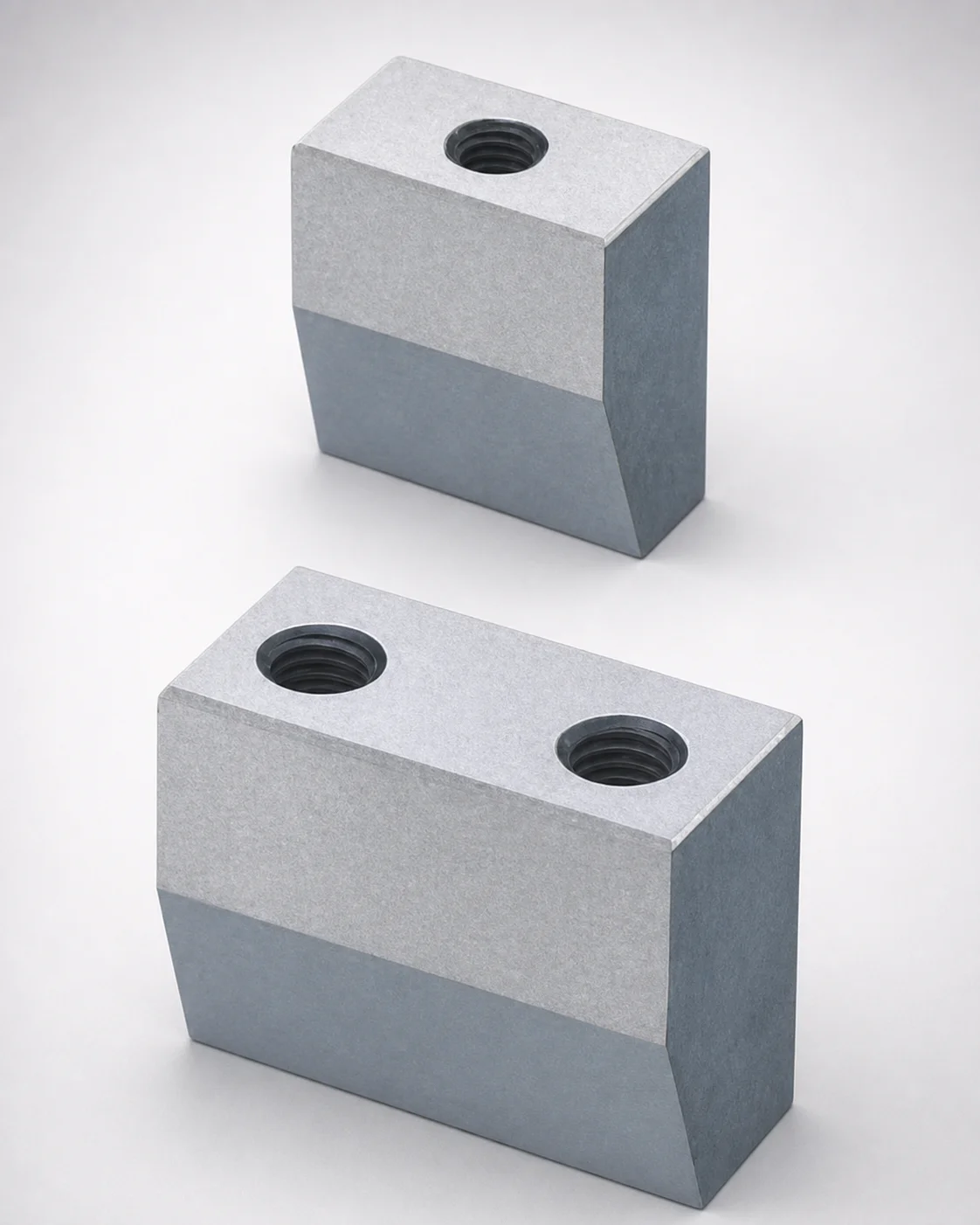
Inlay Type Locking Blocks with Plate Side Setting (Tapped)
Need Custom Specifications?
Our engineering team can help with custom configurations, material selection, and volume pricing.