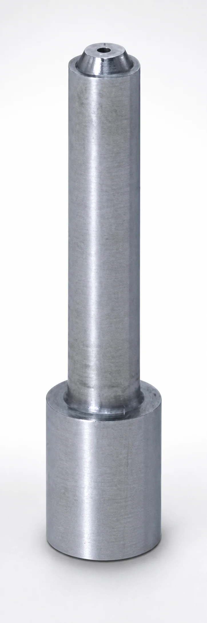
SKH51 Steel Pin-Point Gate Bushings Tapered Tip
Pin-Point Gate Bushings (SKH51 steel) with a tapered tip are designed for controlled angle gate transitions. They support accurate positioning at the gate area to help achieve consistent molding flow and repeatable part quality.
- Angle gate transition geometry with a tapered tip step for stable gate formation
- SKH51 hardened steel construction improves wear resistance in continuous production
- Precision P dimension tolerance ±0.01 for reliable fit in injection mold assemblies
- Used in pin-point gate systems where controlled gate contact and clean mold release matter
Specifications
64 configurations available
| Tip Type | Tip Shape | P Dimension Tolerance | Tip Straight Tolerance | D (Outer diameter) (mm) | A (Taper angle) (°) | B (Length excluding the lengths of head and tip) (mm) | C (Tip length) (mm) | K (Cutting angle) (°) | L (L dimension) (mm) | P (Tip diameter) (mm) | R (Tip R) (mm) | S (Tip angle) (°) | V (Tip diameter) (mm) | type |
|---|---|---|---|---|---|---|---|---|---|---|---|---|---|---|
| Normal | 1A | ±0.01 | 0 to 0.2 | 2.5 | 1 ~ 3 | 4 ~ 6 | 0.2 ~ 0.5 | 20 ~ 30 | 8 ~ 25 | 0.3 ~ 0.6 | - | - | 1.5 ~ 2.4 | - |
| Normal | 1A | ±0.01 | 0 to 0.2 | 3 | 1 ~ 3 | 5 ~ 9 | 0.3 ~ 0.8 | 20 ~ 40 | 10 ~ 40 | 0.5 ~ 0.8 | - | - | 2 ~ 2.9 | - |
| Normal | 1A | ±0.01 | 0 to 0.2 | 4 | 1 ~ 3 | 5 ~ 30 | 0.3 ~ 0.8 | 20 ~ 40 | 10 ~ 40 | 0.6 ~ 1 | - | - | 2.5 ~ 3.9 | - |
| Normal | 1A | ±0.01 | 0 to 0.2 | 5 | 1 ~ 3 | 5 ~ 35 | 0.5 ~ 1.5 | 20 ~ 60 | 15 ~ 60 | 0.8 ~ 1.1 | - | - | 3.5 ~ 4.9 | - |
| Normal | 1A | ±0.01 | 0 to 0.2 | 5 | 1 ~ 3 | 5 ~ 35 | 0.5 ~ 1.5 | 20 ~ 60 | 15 ~ 60 | 1.2 ~ 1.4 | - | - | 3.5 ~ 4.9 | - |
| Normal | 1A | ±0.01 | 0 to 0.2 | 6 | 1 ~ 3 | 5 ~ 50 | 0.5 ~ 1.5 | 20 ~ 60 | 15 ~ 60 | 1 ~ 1.6 | - | - | 4 ~ 5.9 | - |
| Normal | 1A | ±0.01 | 0 to 0.2 | 8 | 1 ~ 3 | 5 ~ 50 | 0.5 ~ 1.5 | 20 ~ 60 | 15 ~ 60 | 1.2 ~ 1.6 | - | - | 4.5 ~ 7.9 | - |
| Normal | 1A | ±0.01 | 0 to 0.2 | 10 | 1 ~ 3 | 5 ~ 50 | 0.5 ~ 1.5 | 20 ~ 60 | 15 ~ 60 | 1.2 ~ 1.6 | - | - | 5 ~ 9.9 | - |
| Normal | 2A | ±0.01 | 0 to 0.2 | 2.5 | 1 ~ 3 | 4 ~ 6 | - | 20 ~ 30 | 8 ~ 25 | 0.3 ~ 0.6 | - | - | - | - |
| Normal | 2A | ±0.01 | 0 to 0.2 | 3 | 1 ~ 3 | 5 ~ 9 | - | 20 ~ 40 | 10 ~ 40 | 0.5 ~ 0.8 | - | - | - | - |
| Normal | 2A | ±0.01 | 0 to 0.2 | 4 | 1 ~ 3 | 5 ~ 30 | - | 20 ~ 40 | 10 ~ 40 | 0.6 ~ 1 | - | - | - | - |
| Normal | 2A | ±0.01 | 0 to 0.2 | 5 | 1 ~ 3 | 5 ~ 35 | - | 20 ~ 60 | 15 ~ 60 | 0.8 ~ 1.1 | - | - | - | - |
| Normal | 2A | ±0.01 | 0 to 0.2 | 5 | 1 ~ 3 | 5 ~ 35 | - | 20 ~ 60 | 15 ~ 60 | 1.2 ~ 1.4 | - | - | - | - |
| Normal | 2A | ±0.01 | 0 to 0.2 | 6 | 1 ~ 3 | 5 ~ 50 | - | 20 ~ 60 | 15 ~ 60 | 1 ~ 1.6 | - | - | - | - |
| Normal | 2A | ±0.01 | 0 to 0.2 | 8 | 1 ~ 3 | 5 ~ 50 | - | 20 ~ 60 | 15 ~ 60 | 1.2 ~ 1.6 | - | - | - | - |
| Normal | 2A | ±0.01 | 0 to 0.2 | 10 | 1 ~ 3 | 5 ~ 50 | - | 20 ~ 60 | 15 ~ 60 | 1.2 ~ 1.6 | - | - | - | - |
| Normal | 3A | ±0.01 | 0 to 0.2 | 2.5 | 1 ~ 3 | 4 ~ 6 | 0.2 ~ 0.5 | 20 ~ 30 | 8 ~ 25 | 0.3 ~ 0.6 | - | 1 ~ 45 | - | - |
| Normal | 3A | ±0.01 | 0 to 0.2 | 3 | 1 ~ 3 | 5 ~ 9 | 0.3 ~ 0.8 | 20 ~ 40 | 10 ~ 40 | 0.5 ~ 0.8 | - | 1 ~ 45 | - | - |
| Normal | 3A | ±0.01 | 0 to 0.2 | 4 | 1 ~ 3 | 5 ~ 30 | 0.3 ~ 0.8 | 20 ~ 40 | 10 ~ 40 | 0.6 ~ 1 | - | 1 ~ 45 | - | - |
| Normal | 3A | ±0.01 | 0 to 0.2 | 5 | 1 ~ 3 | 5 ~ 35 | 0.5 ~ 1.5 | 20 ~ 60 | 15 ~ 60 | 0.8 ~ 1.1 | - | 1 ~ 45 | - | - |
| Normal | 3A | ±0.01 | 0 to 0.2 | 5 | 1 ~ 3 | 5 ~ 35 | 0.5 ~ 1.5 | 20 ~ 60 | 15 ~ 60 | 1.2 ~ 1.4 | - | 1 ~ 45 | - | - |
| Normal | 3A | ±0.01 | 0 to 0.2 | 6 | 1 ~ 3 | 5 ~ 50 | 0.5 ~ 1.5 | 20 ~ 60 | 15 ~ 60 | 1 ~ 1.6 | - | 1 ~ 50 | - | - |
| Normal | 3A | ±0.01 | 0 to 0.2 | 8 | 1 ~ 3 | 5 ~ 50 | 0.5 ~ 1.5 | 20 ~ 60 | 15 ~ 60 | 1.2 ~ 1.6 | - | 1 ~ 60 | - | - |
| Normal | 3A | ±0.01 | 0 to 0.2 | 10 | 1 ~ 3 | 5 ~ 50 | 0.5 ~ 1.5 | 20 ~ 60 | 15 ~ 60 | 1.2 ~ 1.6 | - | 1 ~ 60 | - | - |
| Normal | 4A | ±0.01 | 0 to 0.2 | 2.5 | 1 ~ 3 | 4 ~ 6 | 0.2 ~ 0.5 | 20 ~ 30 | 8 ~ 25 | 0.3 ~ 0.6 | 0.6 ~ 1 | - | - | - |
| Normal | 4A | ±0.01 | 0 to 0.2 | 3 | 1 ~ 3 | 5 ~ 9 | 0.3 ~ 0.8 | 20 ~ 40 | 10 ~ 40 | 0.5 ~ 0.8 | 0.8 ~ 1.5 | - | - | - |
| Normal | 4A | ±0.01 | 0 to 0.2 | 4 | 1 ~ 3 | 5 ~ 30 | 0.3 ~ 0.8 | 20 ~ 40 | 10 ~ 40 | 0.6 ~ 1 | 0.8 ~ 1.5 | - | - | - |
| Normal | 4A | ±0.01 | 0 to 0.2 | 5 | 1 ~ 3 | 5 ~ 35 | 0.5 ~ 1.5 | 20 ~ 60 | 15 ~ 60 | 0.8 ~ 1.1 | 1 ~ 2 | - | - | - |
| Normal | 4A | ±0.01 | 0 to 0.2 | 5 | 1 ~ 3 | 5 ~ 35 | 0.5 ~ 1.5 | 20 ~ 60 | 15 ~ 60 | 1.2 ~ 1.4 | 1 ~ 2 | - | - | - |
| Normal | 4A | ±0.01 | 0 to 0.2 | 6 | 1 ~ 3 | 5 ~ 50 | 0.5 ~ 1.5 | 20 ~ 60 | 15 ~ 60 | 1 ~ 1.6 | 1.5 ~ 3 | - | - | - |
| Normal | 4A | ±0.01 | 0 to 0.2 | 8 | 1 ~ 3 | 5 ~ 50 | 0.5 ~ 1.5 | 20 ~ 60 | 15 ~ 60 | 1.2 ~ 1.6 | 2 ~ 4 | - | - | - |
| Normal | 4A | ±0.01 | 0 to 0.2 | 10 | 1 ~ 3 | 5 ~ 50 | 0.5 ~ 1.5 | 20 ~ 60 | 15 ~ 60 | 1.2 ~ 1.6 | 2.5 ~ 5 | - | - | - |
| Normal | 5A | ±0.01 | 0 to 0.2 | 2.5 | 1 ~ 3 | 4 ~ 6 | 0.2 ~ 0.5 | 20 ~ 30 | 8 ~ 25 | 0.3 ~ 0.6 | - | - | - | - |
| Normal | 5A | ±0.01 | 0 to 0.2 | 3 | 1 ~ 3 | 5 ~ 9 | 0.3 ~ 0.8 | 20 ~ 40 | 10 ~ 40 | 0.5 ~ 0.8 | - | - | - | - |
| Normal | 5A | ±0.01 | 0 to 0.2 | 4 | 1 ~ 3 | 5 ~ 30 | 0.3 ~ 0.8 | 20 ~ 40 | 10 ~ 40 | 0.6 ~ 1 | - | - | - | - |
| Normal | 5A | ±0.01 | 0 to 0.2 | 5 | 1 ~ 3 | 5 ~ 35 | 0.5 ~ 1.5 | 20 ~ 60 | 15 ~ 60 | 0.8 ~ 1.1 | - | - | - | - |
| Normal | 5A | ±0.01 | 0 to 0.2 | 5 | 1 ~ 3 | 5 ~ 35 | 0.5 ~ 1.5 | 20 ~ 60 | 15 ~ 60 | 1.2 ~ 1.4 | - | - | - | - |
| Normal | 5A | ±0.01 | 0 to 0.2 | 6 | 1 ~ 3 | 5 ~ 50 | 0.5 ~ 1.5 | 20 ~ 60 | 15 ~ 60 | 1 ~ 1.6 | - | - | - | - |
| Normal | 5A | ±0.01 | 0 to 0.2 | 8 | 1 ~ 3 | 5 ~ 50 | 0.5 ~ 1.5 | 20 ~ 60 | 15 ~ 60 | 1.2 ~ 1.6 | - | - | - | - |
| Normal | 5A | ±0.01 | 0 to 0.2 | 10 | 1 ~ 3 | 5 ~ 50 | 0.5 ~ 1.5 | 20 ~ 60 | 15 ~ 60 | 1.2 ~ 1.6 | - | - | - | - |
| Acute angle | 1A | - | 0 to 0.05 | 2.5 | 1 ~ 3 | 4 ~ 6 | 0.2 ~ 0.5 | 20 ~ 30 | 8 ~ 25 | 0.3 ~ 0.6 | - | - | 1.5 ~ 2.4 | - |
| Acute angle | 1A | - | 0 to 0.05 | 3 | 1 ~ 3 | 5 ~ 9 | 0.3 ~ 0.8 | 20 ~ 40 | 10 ~ 40 | 0.5 ~ 0.8 | - | - | 2 ~ 2.9 | - |
| Acute angle | 1A | - | 0 to 0.05 | 4 | 1 ~ 3 | 5 ~ 30 | 0.3 ~ 0.8 | 20 ~ 40 | 10 ~ 40 | 0.6 ~ 1 | - | - | 2.5 ~ 3.9 | - |
| Acute angle | 1A | - | 0 to 0.05 | 5 | 1 ~ 3 | 5 ~ 35 | 0.5 ~ 1.5 | 20 ~ 60 | 15 ~ 60 | 0.8 ~ 1.1 | - | - | 3.5 ~ 4.9 | - |
| Acute angle | 1A | - | 0 to 0.05 | 5 | 1 ~ 3 | 5 ~ 35 | 0.5 ~ 1.5 | 20 ~ 60 | 15 ~ 60 | 1.2 ~ 1.4 | - | - | 3.5 ~ 4.9 | - |
| Acute angle | 1A | - | 0 to 0.05 | 6 | 1 ~ 3 | 5 ~ 50 | 0.5 ~ 1.5 | 20 ~ 60 | 15 ~ 60 | 1 ~ 1.6 | - | - | 4 ~ 5.9 | - |
| Acute angle | 1A | - | 0 to 0.05 | 8 | 1 ~ 3 | 5 ~ 50 | 0.5 ~ 1.5 | 20 ~ 60 | 15 ~ 60 | 1.2 ~ 1.6 | - | - | 4.5 ~ 7.9 | - |
| Acute angle | 1A | - | 0 to 0.05 | 10 | 1 ~ 3 | 5 ~ 50 | 0.5 ~ 1.5 | 20 ~ 60 | 15 ~ 60 | 1.2 ~ 1.6 | - | - | 5 ~ 9.9 | - |
| Acute angle | 2A | - | 0 to 0.05 | 2.5 | 1 ~ 3 | 4 ~ 6 | - | 20 ~ 30 | 8 ~ 25 | 0.3 ~ 0.6 | - | - | - | - |
| Acute angle | 2A | - | 0 to 0.05 | 3 | 1 ~ 3 | 5 ~ 9 | - | 20 ~ 40 | 10 ~ 40 | 0.5 ~ 0.8 | - | - | - | - |
Product Guide
Application Scenarios+
These SKH51 steel pin-point gate bushings are used in injection mold tooling where a controlled, repeatable gate transition is critical—especially for angle gate layouts that connect a sprue system to small gate openings.
- Automotive connector and bracket molds: The tapered tip geometry supports stable gate formation and helps maintain consistent melt flow during high-cycle production, reducing variability at the gate area.
- Electronics housings with fine pin-point gates: The tight P dimension tolerance (±0.01) improves locating accuracy in the gate bushing seat, supporting reliable assembly fit and repeatable part ejection behavior.
- Medical device components: When clean gate contact and controlled mold release are required, the tapered tip assists in managing the gate transition shape to promote consistent filling and reduce gate-related defects.
The SKH51 hardened steel base improves wear resistance, making this variant suitable for continuous production conditions where the gate region is actively stressed.
Material & Process Details+
This bushing is manufactured from SKH51 steel, selected for its hardened wear performance in tooling contact zones. SKH51 is commonly used as an HSS-type grade (often aligned with AISI M2 in practical equivalency discussions), balancing hardness with machining wear resistance for gate-related features.
- Heat treatment state: Typically supplied in a hardened condition suitable for precision injection mold components; final hardness depends on the supplier’s heat-treatment cycle.
- Hardness & wear resistance: The hardened SKH51 condition targets high surface hardness for improved resistance to abrasion at the pin-point gate contact.
- Toughness trade-off: As with hardened tool steels, higher hardness generally reduces toughness margin; proper tool steel support and correct machining/handling reduce chipping risk.
Compared with softer steels, SKH51 provides stronger wear resistance for gate bushings; compared with more specialized carbide inserts, it offers better manufacturability and cost efficiency for precision metalworking.
Sizing & Selection Guide+
To select the correct pin-point gate bushing, match the taper geometry and the seating dimensions to your core/cavity gate bushing location and the gate insert interface.
- Diameter match (D): Choose D = 2.5 ~ 10 mm to fit the outer diameter requirement of the gate bushing seat in the mold.
- Tip diameter control (P): The P (tip diameter) range = 0.3 ~ 1.2 mm and fixed P tolerance ±0.01 should be selected based on the targeted pin-point gate thickness/diameter for your part.
- Taper angles (A) and profile: Use A (taper angle) = 1 ~ 3° and select the appropriate Tip Type (Normal or Acute angle), with Cutting angle K = 20 ~ 60° and Tip length C = 0.2 ~ 0.5 / 0.3 ~ 0.8 / 0.5 ~ 1.5 mm to obtain the desired gate transition shape.
- Length selection (B, L): Pick B (excluding head/tip) from 4 ~ 6, 5 ~ 9, 5 ~ 30, 5 ~ 35, or 5 ~ 50 mm and confirm L = 8 ~ 25, 10 ~ 40, or 15 ~ 60 mm to ensure full engagement without over-penetration.
Because P is fixed at ±0.01, verify that your mating seat and gate land can tolerate this precision fit; keep the rest of the profile consistent with your cavity/core gate interface to avoid gate shape drift.
Frequently Asked Questions
How should I choose the pin-point gate tip diameter (P) to control gate thickness in my injection mold design?+
Select P = 0.3 ~ 1.2 mm based on the required gate opening diameter for your part. This product provides a fixed P tolerance of ±0.01, which helps maintain consistent gate formation from shot to shot. If your mold seat is tight, this precision tolerance improves locating repeatability at assembly.
What is the practical difference between the Normal and Acute angle tip types for pin-point gate bushings?+
The Tip Type option (Normal vs Acute angle) changes the gate transition geometry around the tapered region. For applications where you need a more controlled or sharper angle transition, the Acute angle variant helps shape melt entry and stabilize gate formation. Choose based on your target gate land and desired transition profile.
How do taper angle (A) and cutting angle (K) affect gate transition stability?+
Use A (taper angle) = 1 ~ 3° to set the overall taper slope of the tip. Pair it with a suitable Cutting angle K (available ranges include 20 ~ 30°, 20 ~ 40°, and 20 ~ 60°) to refine the transition geometry. Together, these parameters influence how reliably the bushing forms the pin-point gate contact during processing.
Which length dimensions (B and L) should I verify to avoid over-penetration or insufficient engagement?+
Confirm B (length excluding head and tip) from the available bands (e.g., 4 ~ 6, 5 ~ 9, 5 ~ 30, 5 ~ 35, or 5 ~ 50 mm) against your gate bushing cavity depth. Then verify the overall L options (e.g., 8 ~ 25, 10 ~ 40, or 15 ~ 60 mm) to ensure proper engagement without contacting unintended mold components.
What dimensional tolerances should I plan for when fitting the bushing to the mold seat (especially regarding the tip straight tolerance)?+
The product specifies Tip Straight Tolerance ranges of 0 to 0.2 and 0 to 0.05, depending on the configured option. In addition, the P dimension tolerance is fixed at ±0.01, which is critical for gate diameter consistency. Plan seat tolerances and alignment so that the bushing can seat correctly while maintaining the intended pin-point gate geometry.
Related Products
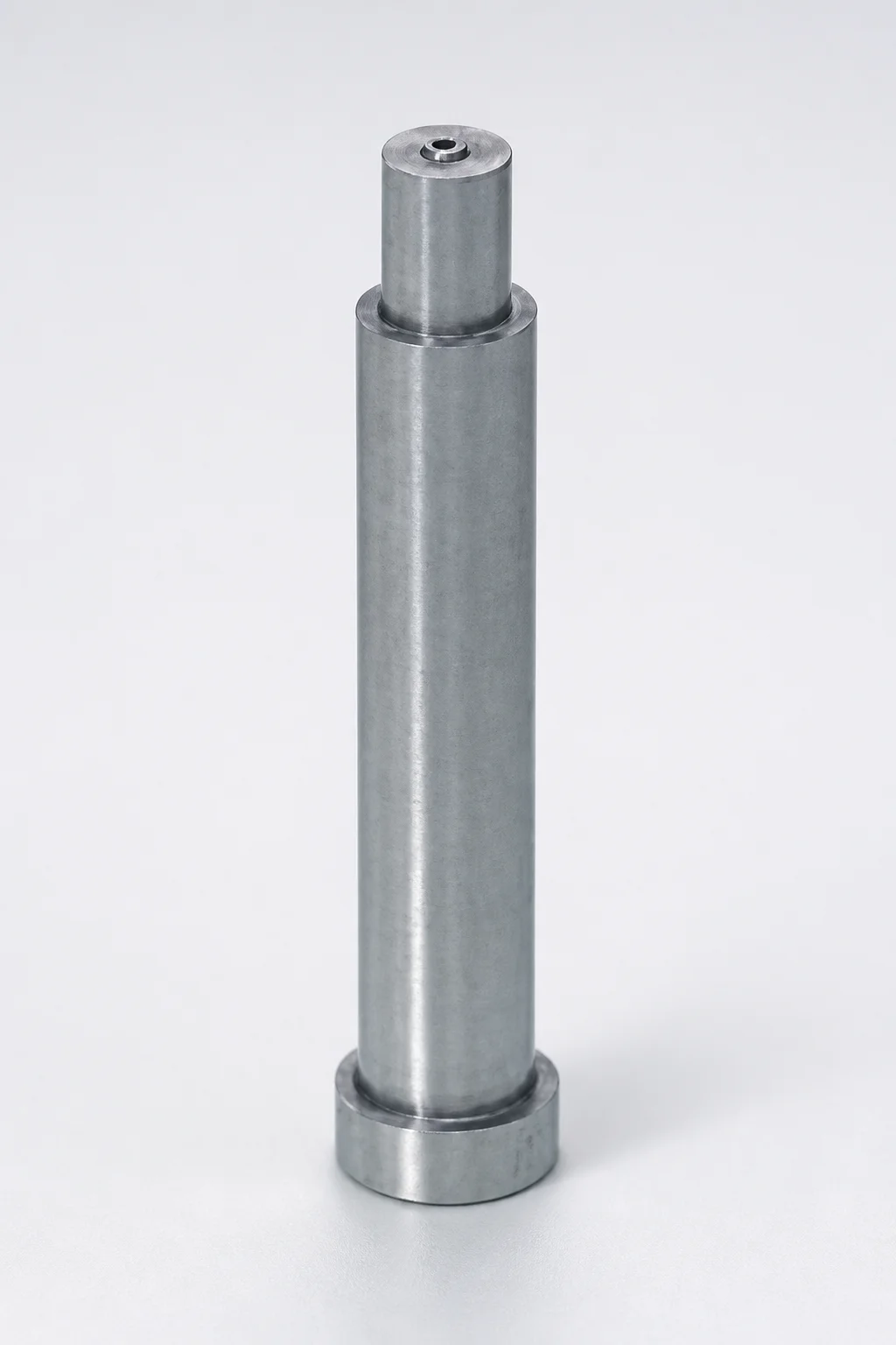
SKH51 Steel Pin-Point Gate Bushings with Head - Round Gate Transition (SR)
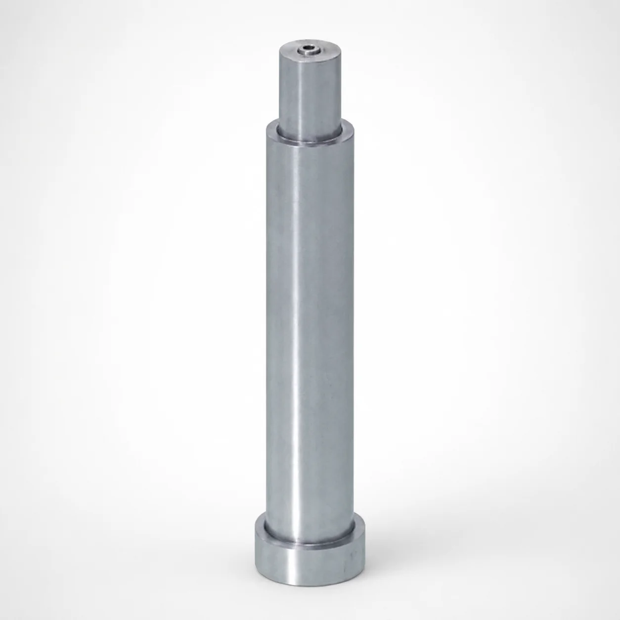
SKH51 Steel Pin-Point Gate Bushings with Head
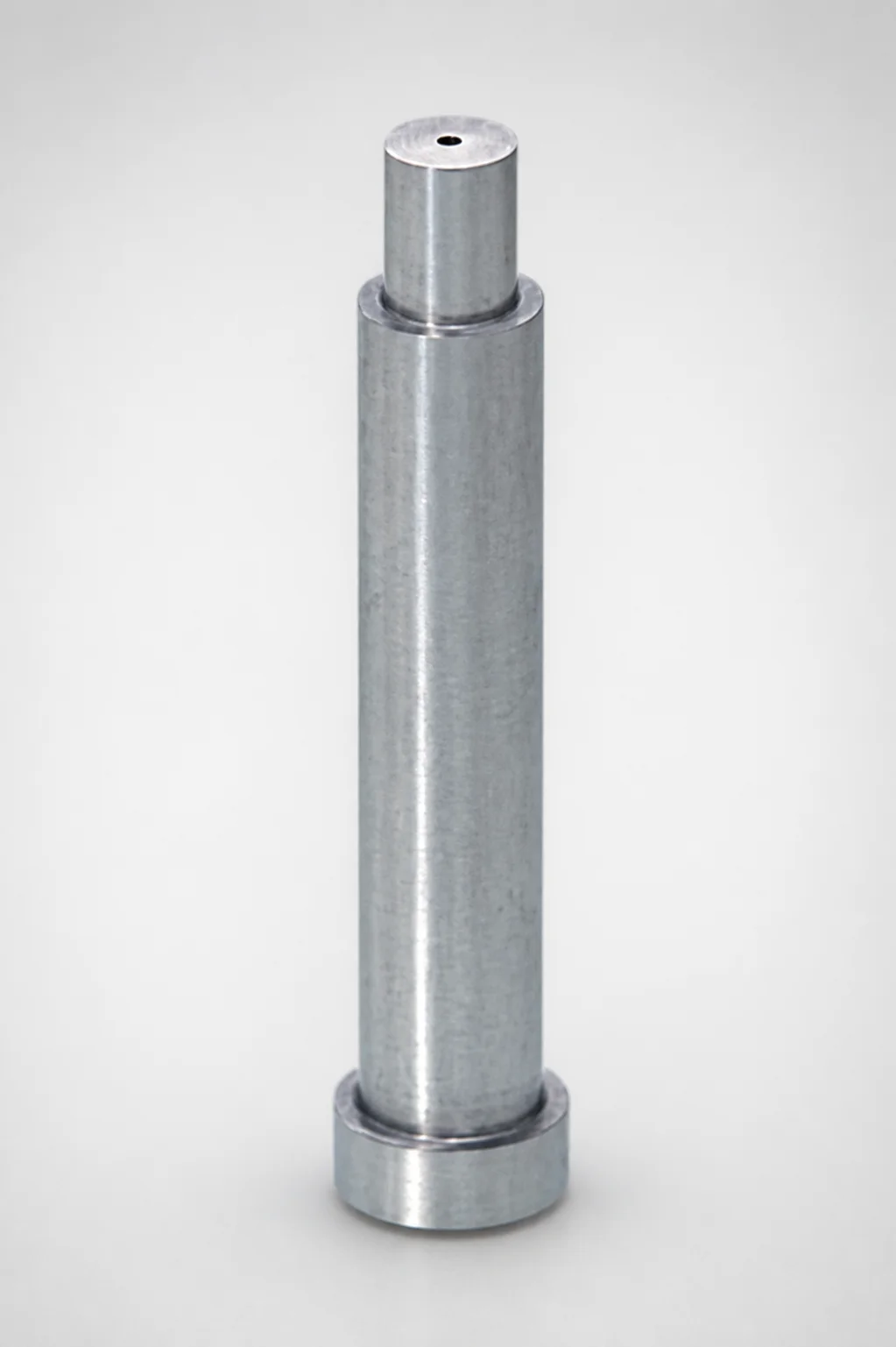
JIS Standard SKH51 Steel Pin-Point Gate Bushings (PGHTBL) with Head
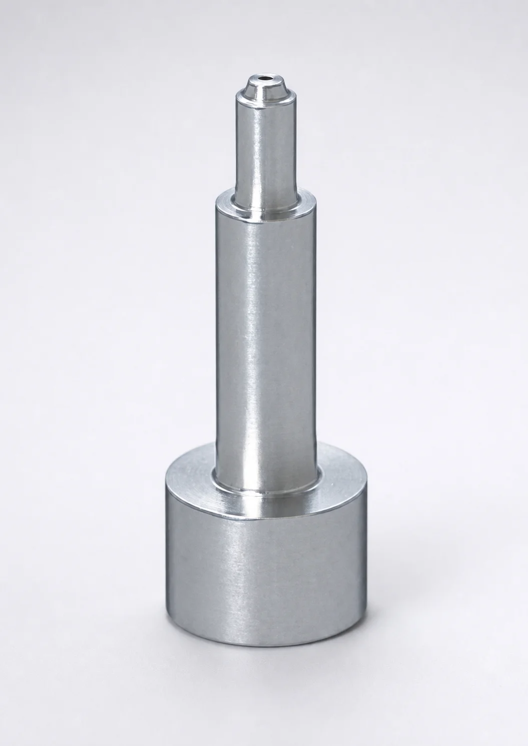
SKH51 Steel Pin-Point Gate Bushings with Head - Round Gate Transition
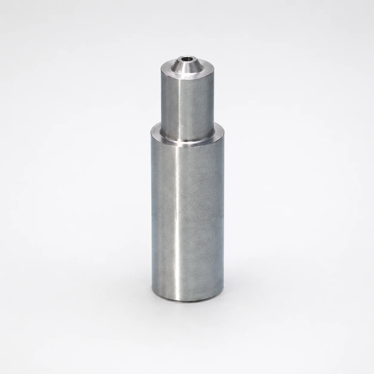
SKH51 Steel Pin-Point Gate Bushings Round Gate Transition SR
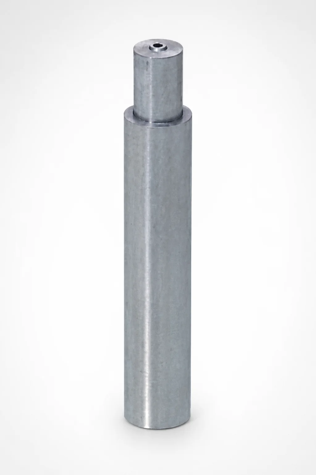
JIS Standard SKH51 Steel Pin-Point Gate Bushings Round Gate Transition SR
Need Custom Specifications?
Our engineering team can help with custom configurations, material selection, and volume pricing.