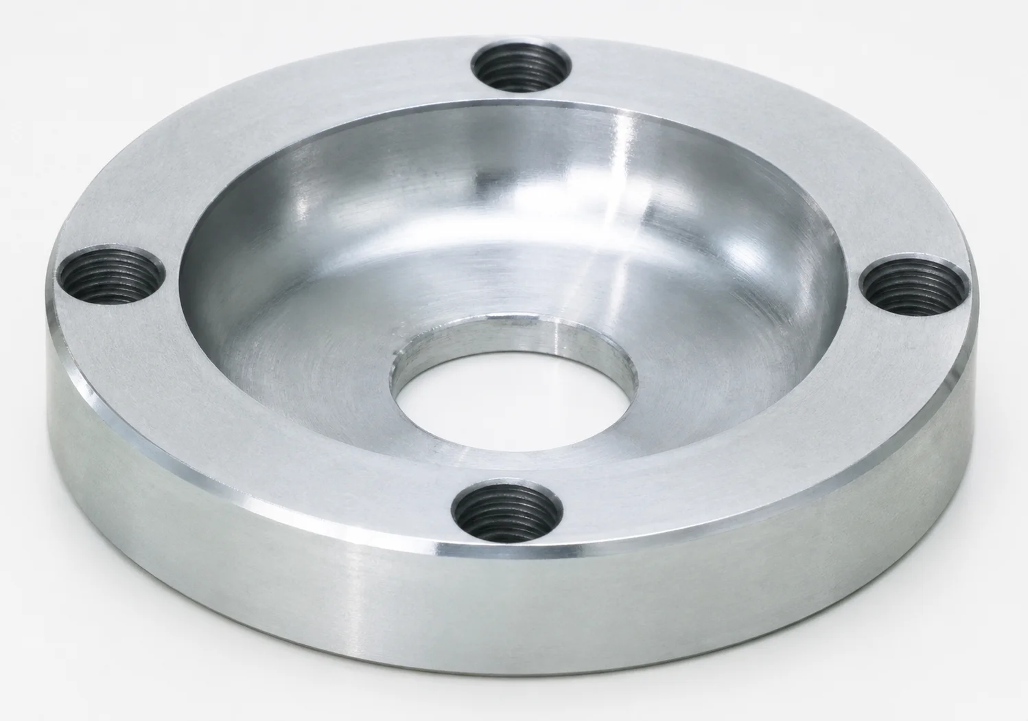
JIS Standard Locating Rings - Counterbore, 4-Bolt Holes
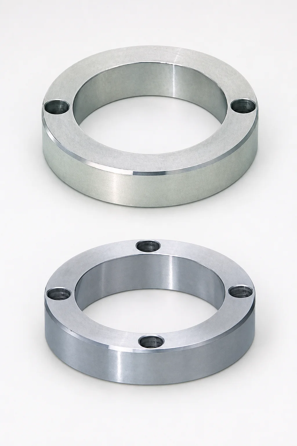
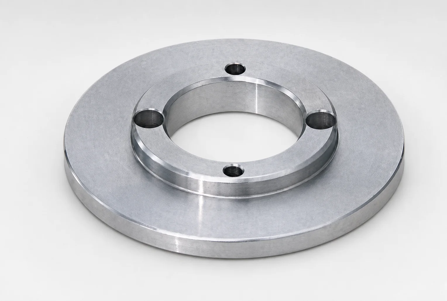
Locating Rings - Counterbore, 4-Bolt Holes provide a stable locating interface for shoulder-type sprues, using a counterbore seating geometry and a standard ring type. The 4-bolt hole pattern supports consistent clamping during production runs.
- Counterbore locating design for repeatable positioning with shoulder-type sprue components
- Standard locating ring configuration to simplify integration with locating applications
- Four-bolt hole mounting layout improves stability under mold handling and cycling
- Suitable for JIS-standard locating setups used in die casting and injection tooling
Specifications
4 configurations available
| T (Height) (mm) | Sale Unit (pieces) | type |
|---|---|---|
| 15 | 10 | - |
| 20 | 10 | - |
| 15 | 20 | - |
| 20 | 20 | - |
Product Guide
Application Scenarios+
This locating ring with a counterbore seating geometry is used to stabilize shoulder-type sprue components inside injection mold tooling. In production, it provides a repeatable interface so the sprue position is maintained during clamping and mold handling.
Common scenarios include:
- Automotive and appliance component injection: 4-bolt fixing improves resistance to micro-movement under high clamp loads, helping keep gate and runner alignment consistent across cycles.
- Die casting and transfer molding tooling: the standard locating ring design supports JIS-style locating setups where predictable seating and secure clamping are critical for sprue performance.
- Multi-cavity molds with frequent maintenance: the fixed 4-bolt hole layout simplifies reassembly and reduces setup variability when changing sprue bush/sprue assemblies.
With available heights of T = 15 or 20 mm, this variant can be matched to the required stack-up of the sprue locating interface and bolster/plate geometry.
Material & Process Details+
The provided specifications identify this as a JIS standard locating ring with counterbore seating and a 4-bolt hole layout, but no steel grade, heat treatment state, or hardness values are included in the input data. Because these details are not specified, material-specific claims (e.g., HRC, nitriding, or quench-and-temper) cannot be stated accurately for this series code.
For locating rings in general, engineers typically select steels based on a balance of wear resistance for repeated clamping and toughness to resist chipping around bolt holes and seating edges. Where multiple materials are offered, the usual trade-off is higher hardness for wear resistance versus improved toughness at lower hardness levels to reduce brittle edge damage.
- Note: Please confirm the steel grade and heat treatment for series 110200174230 if you need hardness (HRC) or surface treatment details for your qualification documentation.
Sizing & Selection Guide+
Selection is primarily driven by the height T of the locating ring, available in 15 mm and 20 mm. Match T to the required mold stack-up so the counterbore seating geometry properly engages the shoulder-type sprue interface without over-compression.
To choose the correct unit size:
- Step 1: Identify the sprue component’s shoulder seating location and the desired engagement depth based on your cavity/core and sprue bushing arrangement.
- Step 2: Select T = 15 mm or T = 20 mm to achieve correct stand-off and alignment of the sprue during clamping.
- Step 3: Verify the 4-bolt hole pattern compatibility with your mold plate/bolt layout so the ring mounts squarely and maintains repeatable positioning.
Since no dimensional tolerances are provided in the input data, rely on your JIS locating standard for fit criteria and ensure your clamping system accounts for any positional tolerance between the ring, plate, and sprue assembly.
Frequently Asked Questions
How do I select between T = 15 mm and T = 20 mm for a shoulder-type sprue locating setup?+
Does the counterbore geometry change how the locating ring seats compared with a non-counterbore locating ring?+
What is the role of the 4-bolt hole pattern when designing the mounting interface?+
Is this locating ring intended for JIS-standard locating applications?+
What material grade, hardness (HRC), or heat treatment should I plan for qualification?+
Related Products
Need Custom Specifications?
Our engineering team can help with custom configurations, material selection, and volume pricing.