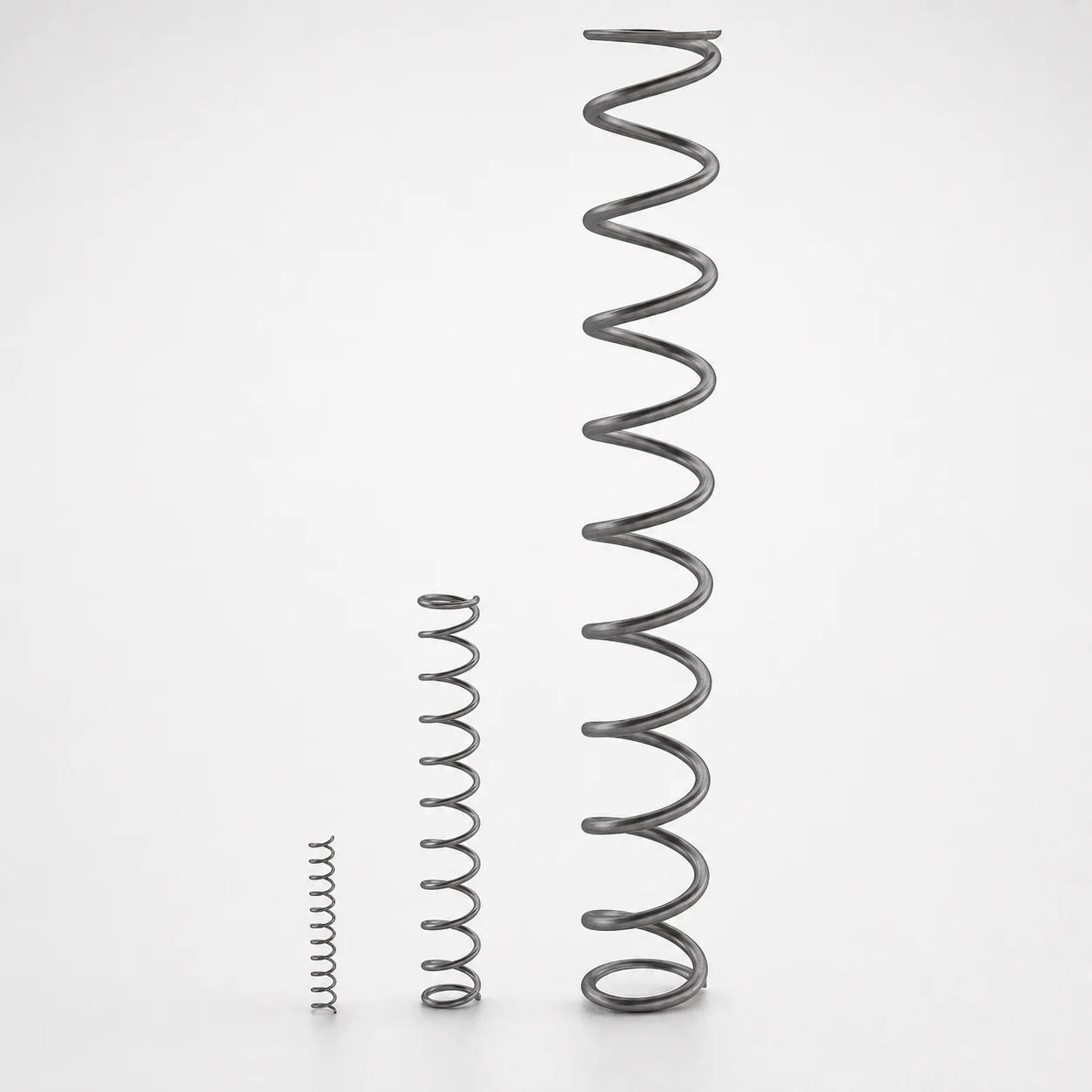
Compression Springs Inch, O.D. and Length Selectable
Compression Springs Inch, O.D. and Length Selectable from Lamina are round-wire compression springs designed to store potential energy and deliver consistent force when loaded. They compress along the spring axis for repeatable performance in fixtures and machinery requiring stable tension.
- Axis-load compression spring design maintains consistent force under cycling
- Steel round-wire construction supports durable operation across demanding assemblies
- Selectable outer diameter (0.078–1 in) and length (0.21–12 in) match varied layouts
- Available end types: Plain, Squared, or Sq. & Gr. for proper seating
Specifications
79 configurations available
| Outer Diameter D (in) | Length L (in) | Type of Ends |
|---|---|---|
| .120 | .62 | b:Squared |
| .120 | .75 | b:Squared |
| .180 | .75 | b:Squared |
| .180 | 1.00 | b:Squared |
| .180 | 1.12 | b:Squared |
| .180 | 1.25 | b:Squared |
| .240 | 1.00 | b:Squared |
| .240 | 1.25 | b:Squared |
| .240 | 1.50 | b:Squared |
| .360 | 1.50 | b:Squared |
| .360 | 1.75 | b:Squared |
| .360 | 2.00 | b:Squared |
| .870 | 12.00 | a:Plain |
| .875 | 10 | a:Plain |
| .735 | 12.00 | a:Plain |
| .620 | 11.50 | a:Plain |
| .518 | 12.00 | a:Plain |
| .375 | 11.50 | a:Plain |
| .360 | 12.00 | a:Plain |
| .300 | 10 | b:Squared |
| .240 | 10 | a:Plain |
| .178 | 10 | a:Plain |
| .66X.94 | .93 | b:Squared |
| .62X.75 | 1.00 | c:Sq. & Gr. |
| .532 | 1.03 | c:Sq. & Gr. |
| .500 | .96 | c:Sq. & Gr. |
| .53X1.03X.86 | 3.50 | c:Sq. & Gr. |
| 1.000 | 2.56 | c:Sq. & Gr. |
| .920 | 2.03 | c:Sq. & Gr. |
| .870 | 3.06 | c:Sq. & Gr. |
| .875 | 2.03 | c:Sq. & Gr. |
| .860 | 2.59 | c:Sq. & Gr. |
| .690 | 4.06 | c:Sq. & Gr. |
| .615 | 2.84 | c:Sq. & Gr. |
| .575 | 2.15 | b:Squared |
| .850 | 1.09 | c:Sq. & Gr. |
| .440 | 2.56 | b:Squared |
| .755 | 2.60 | c:Sq. & Gr. |
| .078 | .56 | a:Plain |
| .078 | .53 | a:Plain |
| .110 | .91 | a:Plain |
| .108 | .81 | a:Plain |
| .170 | .21 | a:Plain |
| .28X.16 | .50 | b:Squared |
| .282 | 1.31 | a:Plain |
| .280 | 1.25 | a:Plain |
| .315 | 1.96 | b:Squared |
| .325 | 2.43 | b:Squared |
| .315 | 2.43 | b:Squared |
| .185 | .93 | a:Plain |
Product Guide
Application Scenarios+
These round-wire compression springs are used in injection mold tooling wherever a compact component must apply controlled, axis-load compression during repeated cycles. Because the force acts along the spring axis, they are well suited for mechanisms that require stable load transfer rather than lateral compliance.
- Fixture and tryout tooling: In bench-top or build-stage jigs, the selectable outer diameter (0.078–1 in) and length (0.21–12 in) help match constrained spaces while maintaining predictable compression stroke for part positioning or retention.
- Core/cavity support and locating features: Choose an end configuration (Plain, Squared, or Sq. & Gr.) to improve seating against flat or guided surfaces, reducing wobble and improving repeatability under cycling.
- Actuation assists in auxiliary mold hardware: For assemblies that require consistent closing or latch bias, the selectable geometry supports integration into varied layouts while keeping the loading direction aligned to the design intent.
Material & Process Details+
The provided datasheet for this series specifies the round-wire compression geometry (outer diameter 0.078–1 in and length 0.21–12 in) and end type options, but it does not list the steel grade, hardness (HRC), heat-treatment state, or coating. Therefore, heat treatment and hardness trade-offs (e.g., quench & tempered vs. nitrided) cannot be stated from the supplied information.
To ensure performance in mold environments, engineering selection should confirm the supplier’s spring material grade and target properties (wear resistance, fatigue life, and toughness). If multiple material/heat-treatment options are offered for this series, compare them by fatigue strength at operating stress and corrosion resistance for the intended duty cycle.
Sizing & Selection Guide+
Select the spring by matching the available space in your mold assembly and the required installed stroke. This series supports outer diameter D from 0.078 to 1 in and free/overall length L from 0.21 to 12 in, allowing sizing across small inserts to larger auxiliary hardware.
- Outer diameter (D): Verify clearance to guide blocks, surrounding pockets, and any surrounding steel features. Use the closest D that still maintains necessary side clearance through the full compression travel.
- Length (L): Choose L to satisfy the installed height. Confirm that the spring can compress the required distance without bottoming before reaching the design load condition.
- End type: Match seating surfaces to the available options: Plain for general contact, Squared for flat seating, or Sq. & Gr. when guided/retained seating geometry is needed.
Tolerance and fit are not provided in the input data; request the specific allowable tolerances and how they affect stack-up versus your mold’s cavity/core spacing and guide clearances.
Frequently Asked Questions
How do I choose the outer diameter (0.078–1 in) for tight mold layouts?+
Select the outer diameter D based on maximum allowed envelope clearance around the spring in the mold assembly. Confirm that clearance remains sufficient through the full compression travel, not just at installed height.
If side interference is possible, prefer the next smaller D within the 0.078–1 in range and verify with the end geometry (Plain, Squared, or Sq. & Gr.).
What end type should I use for reliable seating in a core/cavity mechanism?+
This series offers Plain, Squared, and Sq. & Gr. end types. Use Squared when seating against flat surfaces to improve contact stability is important.
Choose Sq. & Gr. when your design benefits from guided seating geometry to reduce misalignment during cycling.
How should I select the spring length (0.21–12 in) to prevent solid height bottoming?+
From the provided range, pick a spring length L that provides the required installed height and compression stroke without reaching coil bind. Ensure the free length supports the full expected stroke while leaving margin for the design’s stack-up and deflection.
Because free length and installed height relationships depend on spring rate, confirm the required operating deflection with your spring datasheet.
Are hardness (HRC) and heat treatment details provided for this spring series?+
The supplied metadata includes selection ranges for D (0.078–1 in), L (0.21–12 in), and end types (Plain, Squared, Sq. & Gr.), but it does not list the steel grade, hardness, or heat-treatment state.
For fatigue and wear performance in mold use, request the steel specification and the heat-treatment/hardness targets from the supplier before final design freeze.
Can this spring be used for axis-load compression biasing in auxiliary mold hardware?+
Yes. This series is described as a round-wire axis-load compression spring designed to deliver consistent force under cycling in fixtures and machinery. Select D and L to match your constrained envelope, and choose an end type aligned with your seating surfaces (Plain, Squared, or Sq. & Gr.).
Related Products
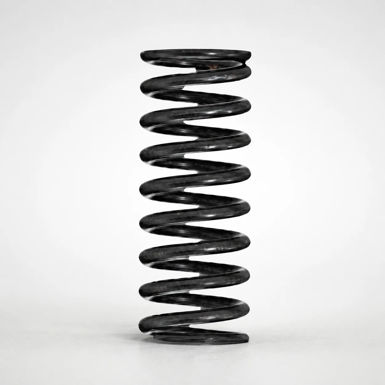
Round Wire Coil Springs - 75% Deflection, WY Series
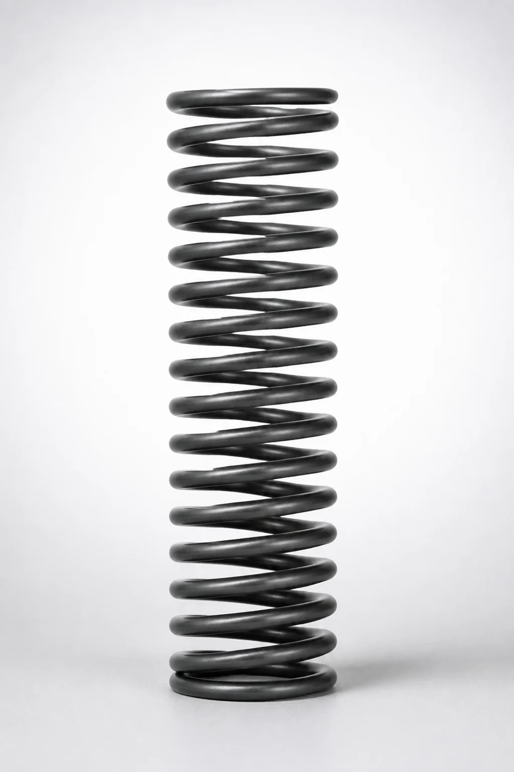
WR Series Round Wire Coil Springs 60% Deflection
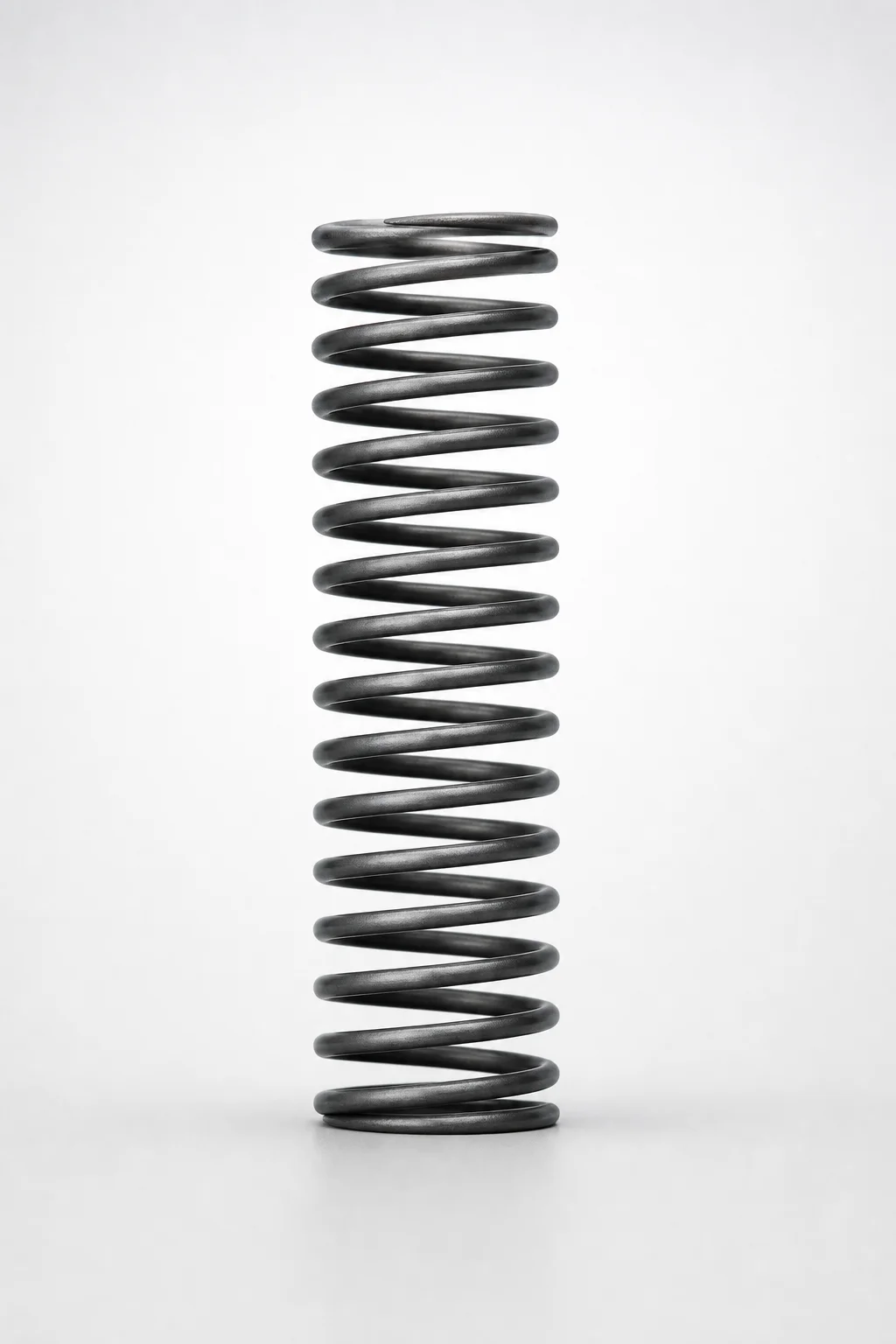
Round Wire Coil Springs - 45% Deflection WF Series
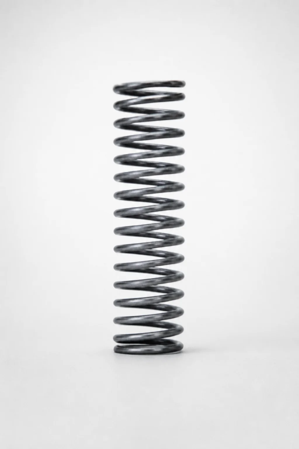
Piano Wire Round Wire Coil Springs - 40% Deflection, WL Series
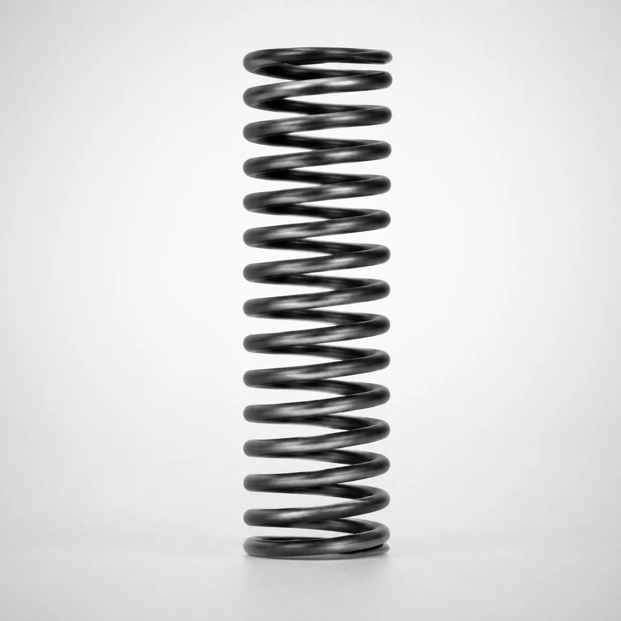
WT Series Round Wire Coil Springs 40% Deflection
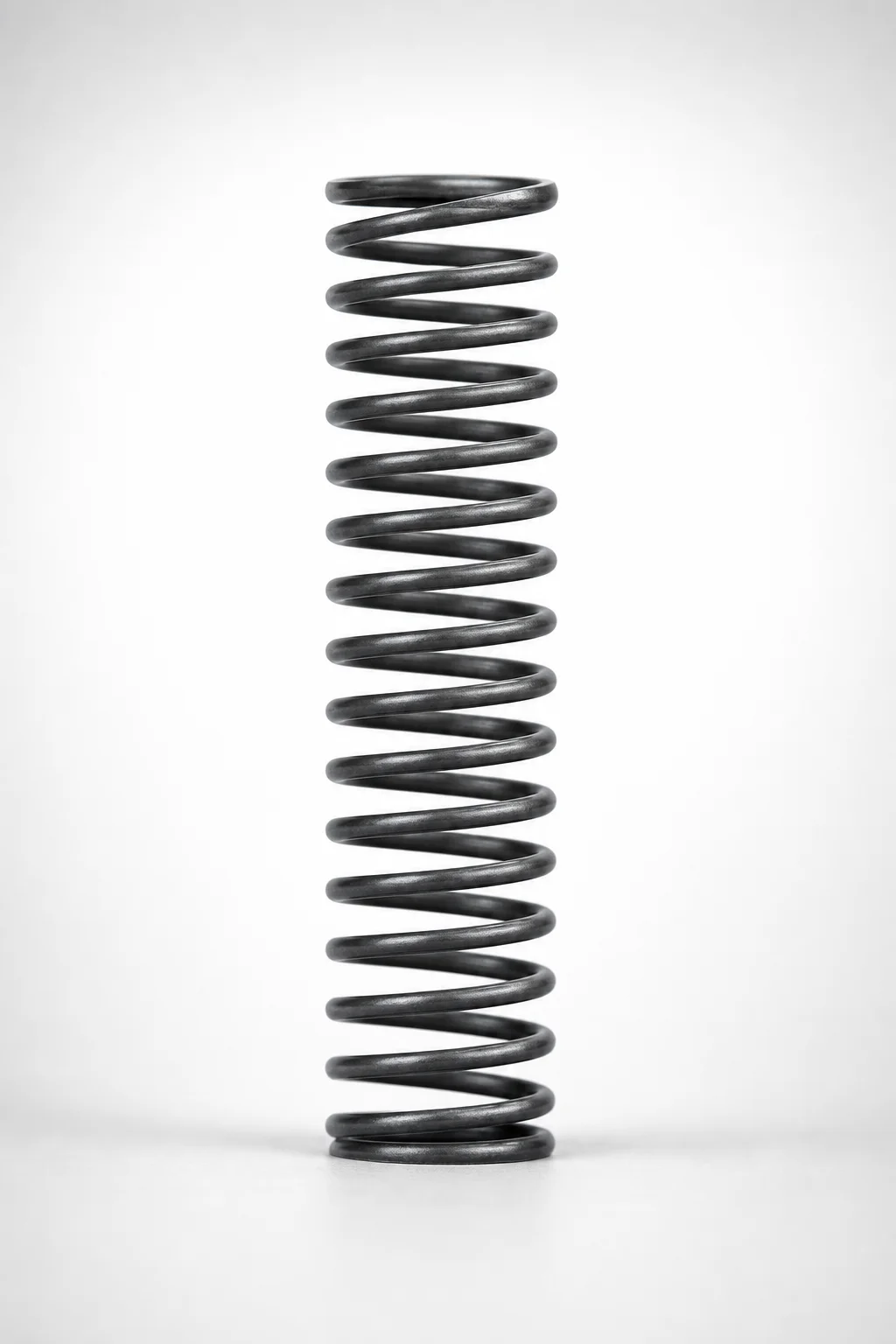
WM Series Round Wire Coil Springs 35% Deflection
Need Custom Specifications?
Our engineering team can help with custom configurations, material selection, and volume pricing.