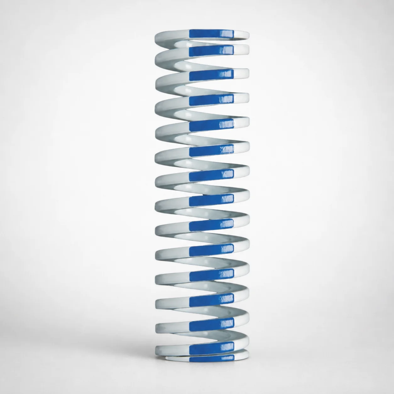
Inch Standard Chrome Silicon Medium Duty Die Spring 40% Deflection
Medium Duty Die Spring (Chrome Silicon) with 40% deflection is designed for controlled load response in inch-based die sets. Its high-strength chromium silicon alloy helps maintain spring performance across repeated forming cycles.
- Medium duty design set to 40% allowable deflection ratio
- High-strength chromium silicon alloy for reliable elastic return
- Consistent spring behavior for stable press and die applications
- Inch series configuration for compatibility with inch die tooling
Specifications
103 configurations available
| Outer Diameter D (in) | Length L (in) | d (Inner diameter) (in) |
|---|---|---|
| 3/8" | 1" | 3/16" |
| 3/8" | 1-1/4" | 3/16" |
| 3/8" | 1-1/2" | 3/16" |
| 3/8" | 1-3/4" | 3/16" |
| 3/8" | 2" | 3/16" |
| 3/8" | 2-1/2" | 3/16" |
| 3/8" | 3" | 3/16" |
| 3/8" | 12" | 3/16" |
| 1/2" | 1" | 9/32" |
| 1/2" | 1-1/4" | 9/32" |
| 1/2" | 1-1/2" | 9/32" |
| 1/2" | 1-3/4" | 9/32" |
| 1/2" | 2" | 9/32" |
| 1/2" | 2-1/2" | 9/32" |
| 1/2" | 3" | 9/32" |
| 1/2" | 3-1/2" | 9/32" |
| 1/2" | 4-1/2" | 9/32" |
| 1/2" | 5-1/2" | 9/32" |
| 1/2" | 6-1/2" | 9/32" |
| 1/2" | 7-1/2" | 9/32" |
| 1/2" | 12" | 9/32" |
| 5/8" | 1" | 11/32" |
| 5/8" | 1-1/4" | 11/32" |
| 5/8" | 1-1/2" | 11/32" |
| 5/8" | 1-3/4" | 11/32" |
| 5/8" | 2" | 11/32" |
| 5/8" | 2-1/2" | 11/32" |
| 5/8" | 3" | 11/32" |
| 5/8" | 3-1/2" | 11/32" |
| 5/8" | 4" | 11/32" |
| 5/8" | 12" | 11/32" |
| 3/4" | 1" | 3/8" |
| 3/4" | 1-1/4" | 3/8" |
| 3/4" | 1-1/2" | 3/8" |
| 3/4" | 1-3/4" | 3/8" |
| 3/4" | 2" | 3/8" |
| 3/4" | 2-1/2" | 3/8" |
| 3/4" | 3" | 3/8" |
| 3/4" | 3-1/2" | 3/8" |
| 3/4" | 4" | 3/8" |
| 3/4" | 4-1/2" | 3/8" |
| 3/4" | 5" | 3/8" |
| 3/4" | 5-1/2" | 3/8" |
| 3/4" | 6" | 3/8" |
| 3/4" | 6-1/2" | 3/8" |
| 3/4" | 7-1/2" | 3/8" |
| 3/4" | 12" | 3/8" |
| 1" | 1" | 1/2" |
| 1" | 1-1/4" | 1/2" |
| 1" | 1-1/2" | 1/2" |
Product Guide
Application Scenarios+
This medium-duty coil die spring is used in inch-based injection molding and pressing tooling where a controlled return force and predictable deflection are essential. The 40% deflection setting makes it suitable for stop-and-go motions such as actuation and retraction in stripper systems, slide-related components, and die-set internals that must recover consistently cycle after cycle.
- Automotive and industrial connector housings: In multi-cavity press stations, springs tuned for ~40% allowable deflection help stabilize closure/load characteristics, reducing variability in stripper return and improving dimensional consistency across runs.
- Consumer electronics housings: For thin-walled parts that require precise die-set behavior, the chrome silicon alloy supports reliable elastic response under repeated forming cycles.
- General in-mold ejector/stripper mechanisms: Its medium duty profile is well suited when you need controlled load without the extreme compliance of light-duty springs.
Material & Process Details+
Built from a chrome silicon alloy, this die spring is engineered for high elastic strength and stable performance under repeated loading. Chrome silicon steels are selected for their balance of wear resistance and toughness, supporting reliable force recovery in tooling environments where springs see constant compression and release.
The exact hardness (HRC) and specific heat-treat condition are not provided in the supplied specifications; however, chrome silicon die springs are typically manufactured by forming to size and then undergoing standard spring heat treatment (e.g., quench and temper or equivalent spring tempering) to achieve the required elastic properties and dimensional stability.
- Strength vs. toughness trade-off: Higher hardness generally improves wear and fatigue life, while adequate tempering maintains toughness to resist cracking.
- Wear behavior: Alloying improves resistance to surface degradation from repeated cyclic contact.
Sizing & Selection Guide+
Select the spring by matching its key dimensions to the mechanical space and deflection path in your die-set. Use the provided ranges: outer diameter D = 1 ~ 5 in, length L = 1 ~ 12 in, and inner diameter d = 1 ~ 11 in.
1) Confirm the available envelope in the die: the spring OD (D) must fit within surrounding guides and cavities. 2) Ensure the guide/mandrel clearance by verifying the ID (d) clears the mating component with the intended working space. 3) Set the installed free/loaded length so the working compression corresponds to the spring’s intended ~40% allowable deflection ratio, avoiding under- or over-compression.
- Tolerance/fit: The data provided lists dimensional ranges only; confirm the final tolerance requirements with your spring supplier drawing for proper fit and alignment.
- Configurable sizing: D, d, and L are variable within the stated ranges to suit different die designs.
Frequently Asked Questions
For inch die sets, how do I verify that the 40% deflection spring matches the expected working compression?+
This spring is specified for a 40% allowable deflection ratio, meaning your die design should target a working compression level aligned with that controlled deflection intent. Use the installed length based on your cavity/core stack-up to estimate the compression under load. Avoid designs that drive the spring beyond its intended compression, as that can change return behavior.
What dimension should I prioritize to prevent interference when selecting the spring for an ejector/stripper mechanism?+
Prioritize outer diameter (D) first to confirm physical clearance in the die-set, because D ranges from 1 ~ 5 in. Next verify the inner diameter (d) (range 1 ~ 11 in) for clearance over the guiding element. Finally confirm length L (range 1 ~ 12 in) matches available stroke space and installed height.
How does the chrome silicon alloy choice support repeated cycling in forming or press operations?+
The spring uses a chrome silicon alloy designed to maintain elastic return under repeated compression cycles. This alloy selection is intended to provide stable spring behavior for controlled die-set response. For best outcomes, select the spring size so the working deflection stays aligned with the stated 40% deflection target.
Can I use this spring in multi-cavity setups where return force uniformity is critical?+
Yes—medium-duty die springs with controlled deflection help maintain consistent return characteristics in inch tooling applications. For multi-cavity stations, choose matching D, d, and L values across stations so the force-deflection behavior stays comparable. Use the 1 ~ 5 in (D), 1 ~ 11 in (d), and 1 ~ 12 in (L) ranges to standardize your design.
What are the key risks if the chosen spring dimensions do not fit the die envelope?+
If OD (D) is too large, the spring can interfere with surrounding components, especially near guides or die walls. If ID (d) is too small, it may bind on the guiding feature or reduce alignment during compression. If L is mismatched to installed height, the spring may not achieve the intended ~40% deflection behavior, leading to inconsistent return force.
Related Products
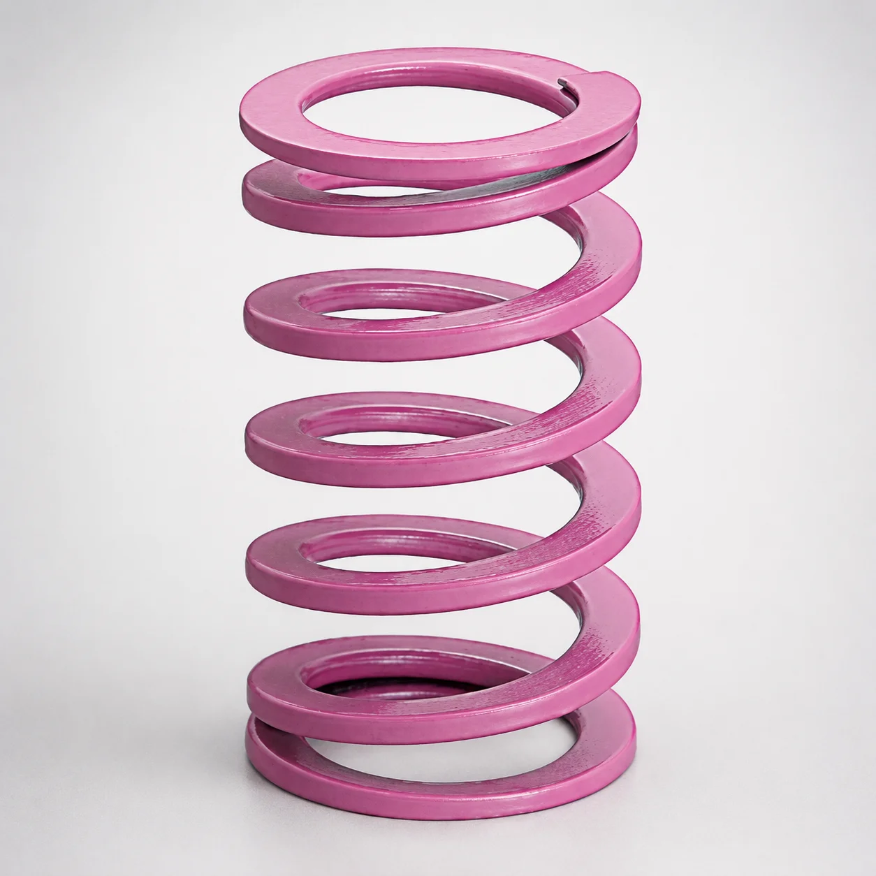
JIS Standard Chrome Silicon Medium Duty Die Spring 60% Deflection
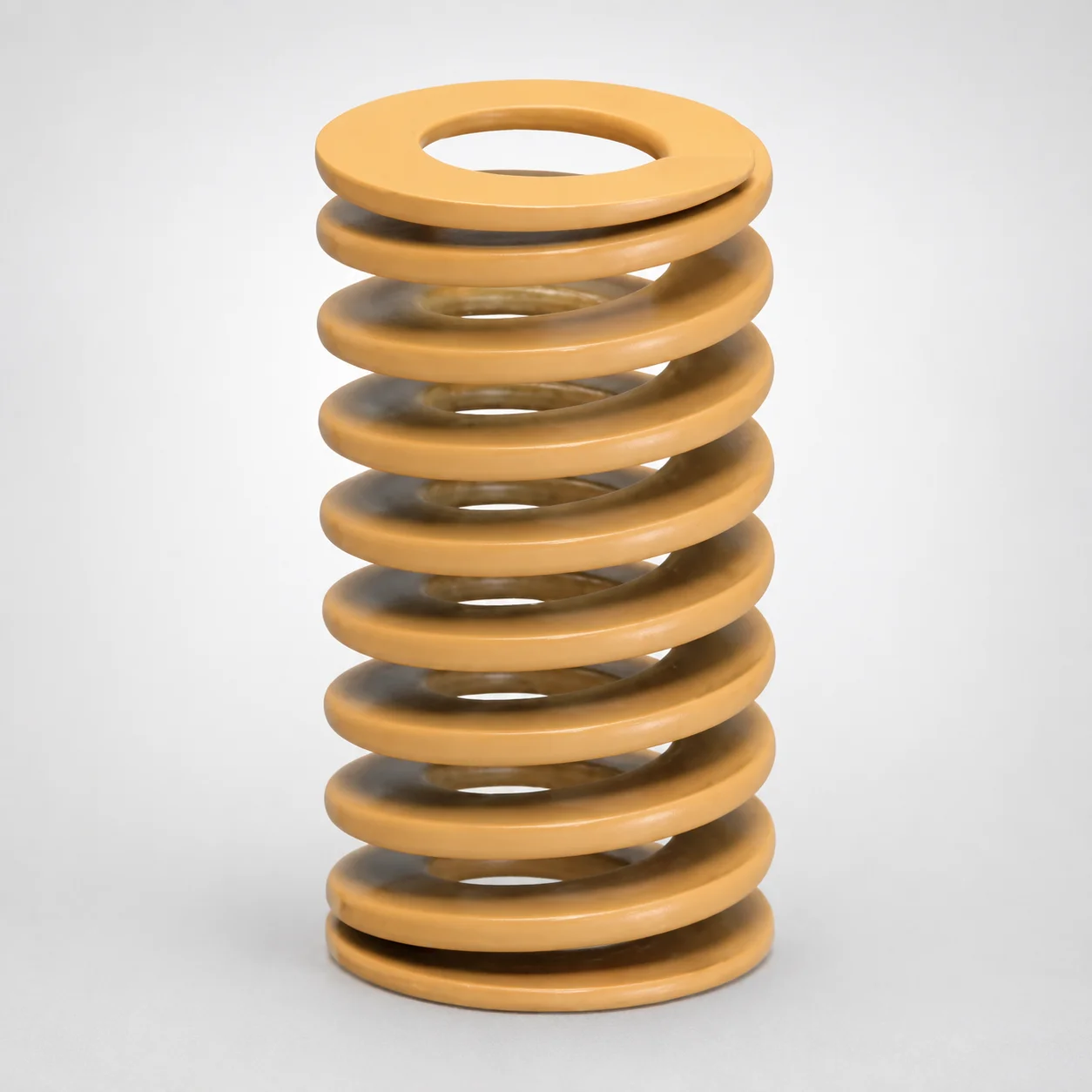
JIS Standard Chrome Silicon Medium Duty Die Spring - 50% Deflection
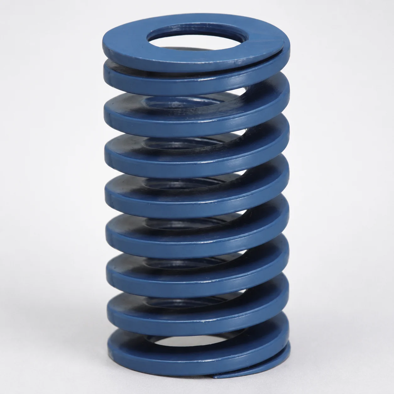
JIS Standard Chrome Silicon Steel Medium Duty Die Spring - 40% Deflection
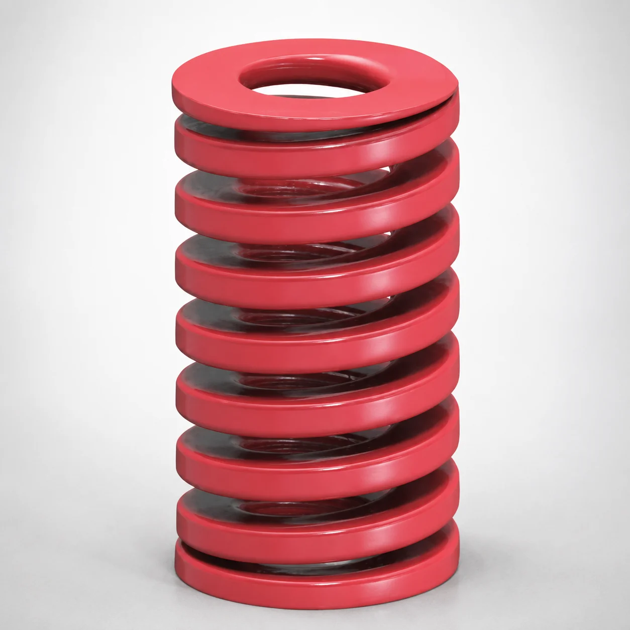
JIS Standard Medium Duty Die Spring 32% Deflection Chrome Silicon Coil Springs
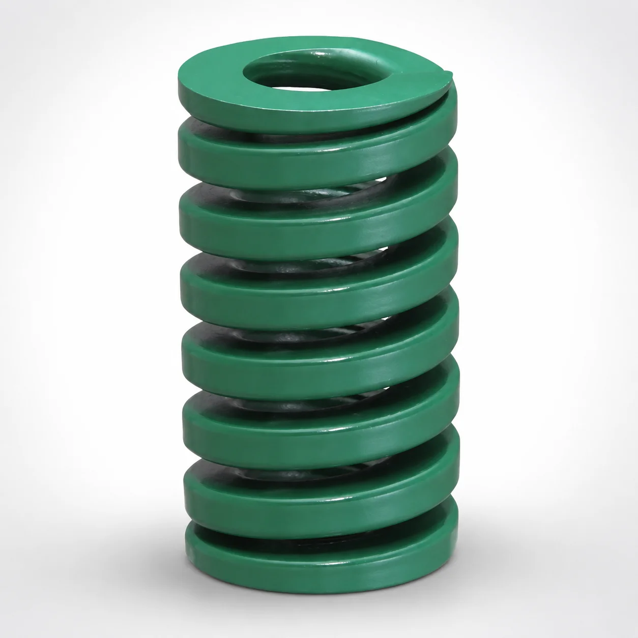
JIS Standard Heavy Duty Die Spring 24% Deflection
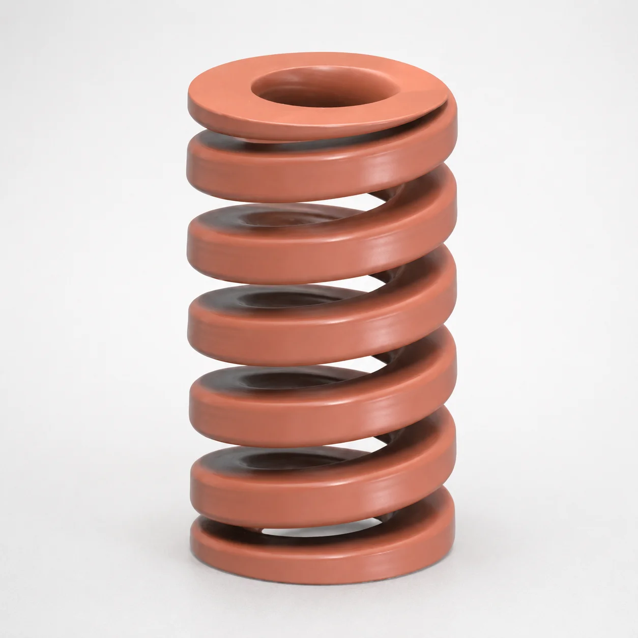
JIS Standard Chrome Silicon Oil-Tempered Wire Heavy Duty Die Spring 20% Deflection
Need Custom Specifications?
Our engineering team can help with custom configurations, material selection, and volume pricing.