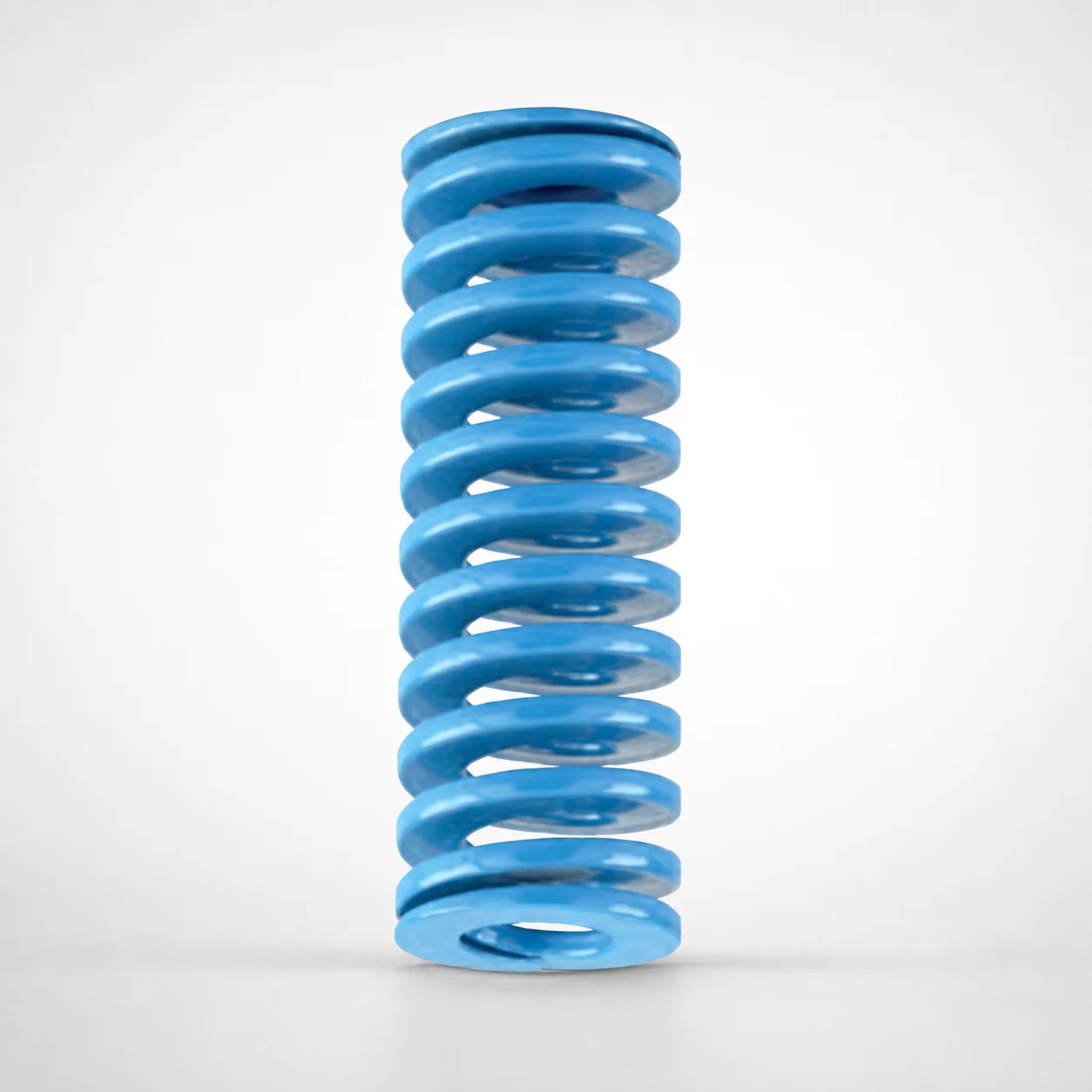
JIS Standard Light Duty Die Spring 40% Deflection
Light Duty Die Spring 40% Deflection (JIS standard) from DANLY IEM uses chrome silicon construction to deliver stable, repeatable force under light-load die applications. Designed for consistent press operation, it helps maintain reliable tool return and part cycle performance.
- 40% allowable deflection ratio supports light-load tooling cycles
- Chrome silicon spring steel improves resilience and fatigue resistance
- Compatible with JIS die spring assemblies for straightforward substitution
- Ideal for die sets, forming tools, and mechanical industrial equipment
Specifications
201 configurations available
| type | Outer Diameter D (mm) | Length L (mm) | d (Inner diameter) (mm) |
|---|---|---|---|
| - | 10 | 20 | 5 |
| - | 10 | 25 | 5 |
| - | 10 | 30 | 5 |
| - | 10 | 35 | 5 |
| - | 10 | 40 | 5 |
| - | 10 | 45 | 5 |
| - | 10 | 50 | 5 |
| - | 10 | 55 | 5 |
| - | 10 | 60 | 5 |
| - | 10 | 65 | 5 |
| - | 10 | 70 | 5 |
| - | 10 | 75 | 5 |
| - | 10 | 80 | 5 |
| - | 12 | 20 | 6 |
| - | 12 | 25 | 6 |
| - | 12 | 30 | 6 |
| - | 12 | 35 | 6 |
| - | 12 | 40 | 6 |
| - | 12 | 45 | 6 |
| - | 12 | 50 | 6 |
| - | 12 | 55 | 6 |
| - | 12 | 60 | 6 |
| - | 12 | 65 | 6 |
| - | 12 | 70 | 6 |
| - | 12 | 75 | 6 |
| - | 12 | 80 | 6 |
| - | 14 | 25 | 7 |
| - | 14 | 30 | 7 |
| - | 14 | 35 | 7 |
| - | 14 | 40 | 7 |
| - | 14 | 45 | 7 |
| - | 14 | 50 | 7 |
| - | 14 | 55 | 7 |
| - | 14 | 60 | 7 |
| - | 14 | 65 | 7 |
| - | 14 | 70 | 7 |
| - | 14 | 75 | 7 |
| - | 14 | 80 | 7 |
| - | 14 | 90 | 7 |
| - | 16 | 100 | 8 |
| - | 16 | 25 | 8 |
| - | 16 | 30 | 8 |
| - | 16 | 35 | 8 |
| - | 16 | 40 | 8 |
| - | 16 | 45 | 8 |
| - | 16 | 50 | 8 |
| - | 16 | 55 | 8 |
| - | 16 | 60 | 8 |
| - | 16 | 65 | 8 |
| - | 16 | 70 | 8 |
Product Guide
Application Scenarios+
This light duty die spring is used in injection mold tooling primarily as a return and positioning element inside die-set and slide mechanisms where low to moderate closing loads are required. The 40% deflection design supports stable force behavior during light-load press cycles, helping reduce variance in cycle time and part ejection timing.
- Automotive connector and small housing tooling: Suitable for stripper plate, ejector support, or slide return where the spring must repeatedly return light components without excessive stress.
- Consumer electronics enclosures: Works well in forming inserts and mechanical guide systems that benefit from reliable return force at relatively shallow working stroke.
- General industrial die sets: A practical substitution for JIS die spring assemblies when consistent light-load performance and repeatability are required.
Its chrome silicon spring construction is well-suited to maintain resilience and fatigue resistance under frequent cycling.
Material & Process Details+
This JIS standard light duty die spring is manufactured using chrome silicon spring steel, selected for its excellent resilience and fatigue resistance in repeatedly loaded tooling components. Chrome silicon steels are typically chosen where stable spring force is required under cyclic stress, such as die return elements and low-load press mechanisms.
- Hardness: Not provided in the supplied specifications, so hardness in HRC cannot be stated for this exact part.
- Heat treatment: Not provided in the supplied specifications; therefore, the exact condition (e.g., pre-hardened vs. quenched & tempered vs. nitrided) cannot be confirmed from the given data.
- Trade-offs: For light duty applications, the spring is optimized for durability and repeatability at controlled deflection rather than maximum load capacity.
If alternative spring steel options are required for higher-load duty, confirm the steel grade and heat treatment state with the supplier so hardness and wear/toughness balance match your cycle requirements.
Sizing & Selection Guide+
Select the die spring dimensions by matching the outer diameter (D), inner diameter (d), and free length (L) to the spring pocket and the functional stroke of your tool return system. The available ranges for this series are D = 10–60 mm, d = 5–30 mm, and L = 20–300 mm.
- Check geometric clearance: Use d to ensure sufficient clearance over the guide rod or center feature, and D to fit within the surrounding housing or spring seat.
- Verify working stroke: Confirm the spring will operate within the 40% allowable deflection ratio referenced by the JIS light duty design to maintain stable force under light-load cycling.
- Length matching: Choose L so the stack height during installation allows the intended working deflection without bottoming.
Tolerances are not specified in the provided data; for press-fit seats or tight guide systems, request the drawing-level tolerances to ensure proper assembly fit and consistent return performance.
Frequently Asked Questions
How do I size this JIS light duty die spring to use the 40% allowable deflection safely in a mold tool?+
Because this series is specified as a 40% deflection light duty die spring, size the installation so the working stroke stays within that allowable ratio during cycling. Use the selected L (20–300 mm) to prevent coil bind/bottoming and verify clearances with d (5–30 mm) over your guide or center feature.
Confirm the deflection amount under your load in the tool design stage, since the provided specs cover dimensional ranges but not force curves.
What outer diameter (D) and inner diameter (d) combinations are available for this die spring series?+
The available dimensional ranges for this product series are D = 10–60 mm (outer diameter) and d = 5–30 mm (inner diameter). Choose d based on the clearance needed for the guide rod/center post and select D to fit the spring pocket and seat.
For a specific mold cavity/core interface, validate that your pocket wall thickness and seating geometry accommodate the chosen diameter.
Can this spring be substituted into existing JIS die spring assemblies for die sets and light-load return mechanisms?+
Yes. The product description states it is a JIS standard light duty die spring and is intended to be compatible with JIS die spring assemblies for straightforward substitution.
To ensure interchangeability, match the key dimensions D (10–60 mm), d (5–30 mm), and L (20–300 mm) to your existing assembly drawing.
What material properties (steel grade, hardness in HRC, heat treatment condition) apply to this die spring?+
The current specifications indicate chrome silicon spring construction for improved resilience and fatigue resistance. However, the provided data does not include the exact steel grade, hardness value in HRC, or the heat treatment state (e.g., quenched & tempered, nitrided).
If your application requires confirmed hardness for wear/deflection stability, request the material grade and hardness/heat-treatment documentation for this exact series and size.
How do I select free length L for reliable return force without coil bind during mold cycles?+
Select L = 20–300 mm so the spring can compress to the required working deflection while leaving sufficient clearance. Use d and D to ensure correct seating and guide alignment, because misalignment can increase friction and reduce repeatability.
Since tolerance and force data are not included in the provided specs, it’s recommended to verify fit/tolerance requirements and validate deflection behavior under your actual cycle load.
Related Products
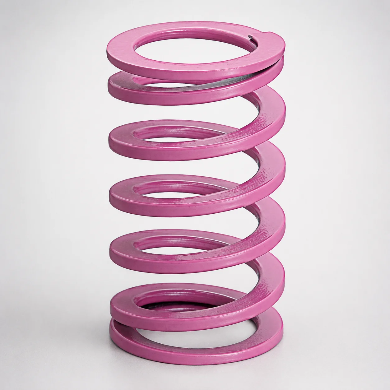
JIS Standard Chrome Silicon Medium Duty Die Spring 60% Deflection
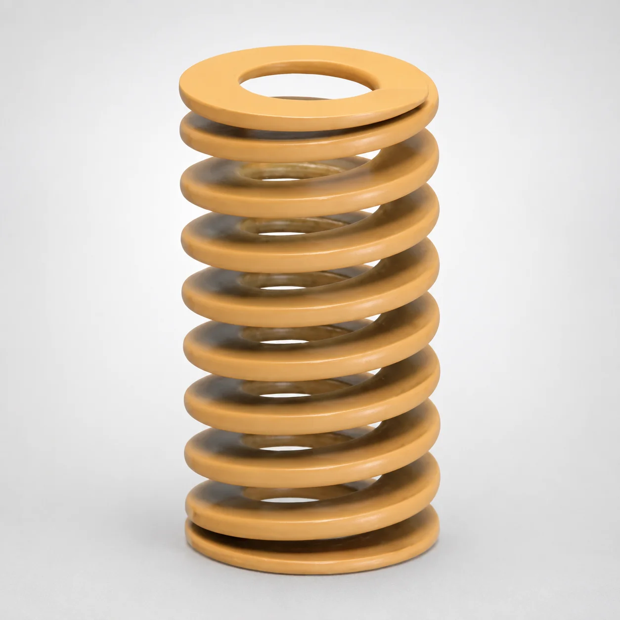
JIS Standard Chrome Silicon Medium Duty Die Spring - 50% Deflection
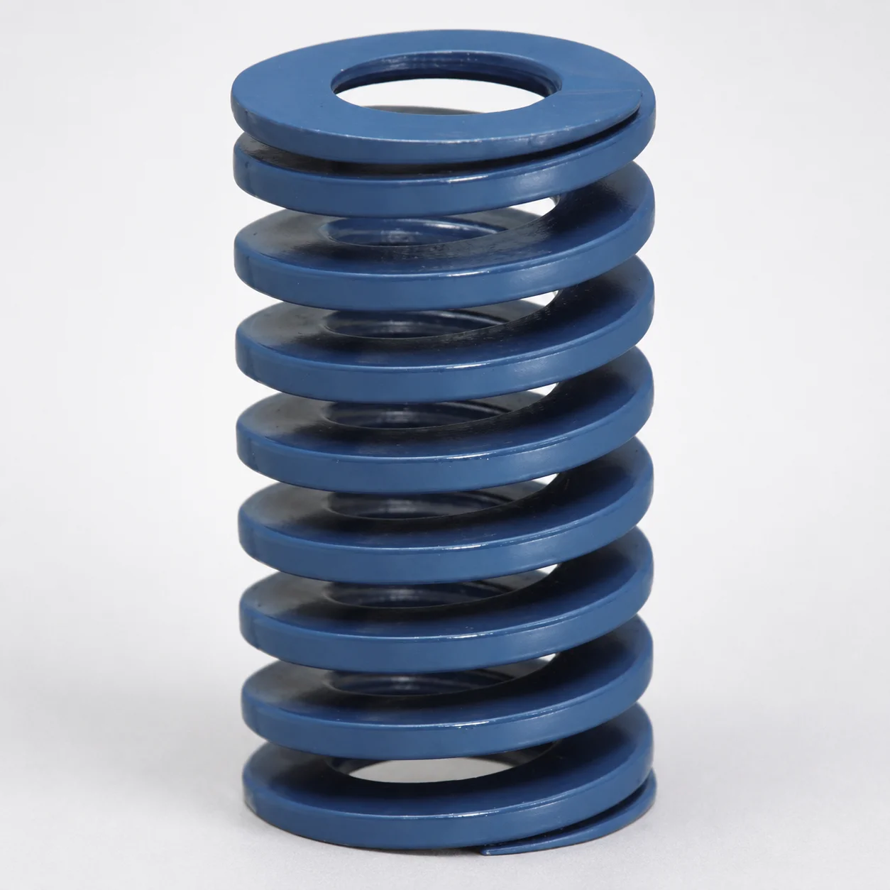
JIS Standard Chrome Silicon Steel Medium Duty Die Spring - 40% Deflection
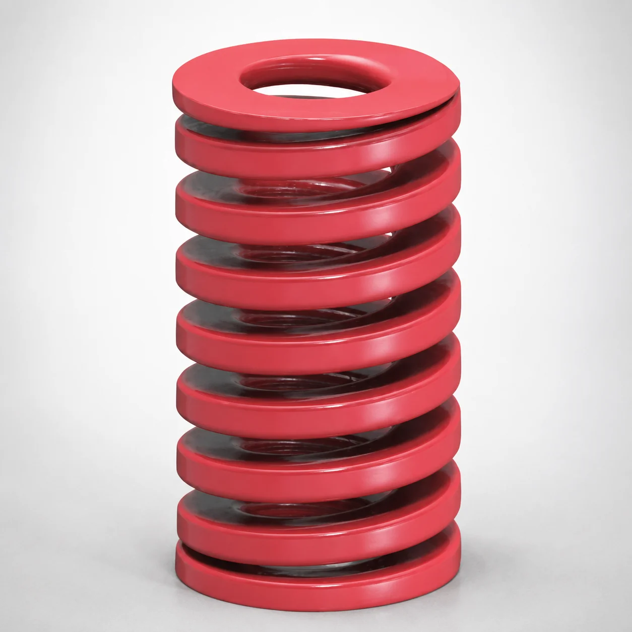
JIS Standard Medium Duty Die Spring 32% Deflection Chrome Silicon Coil Springs
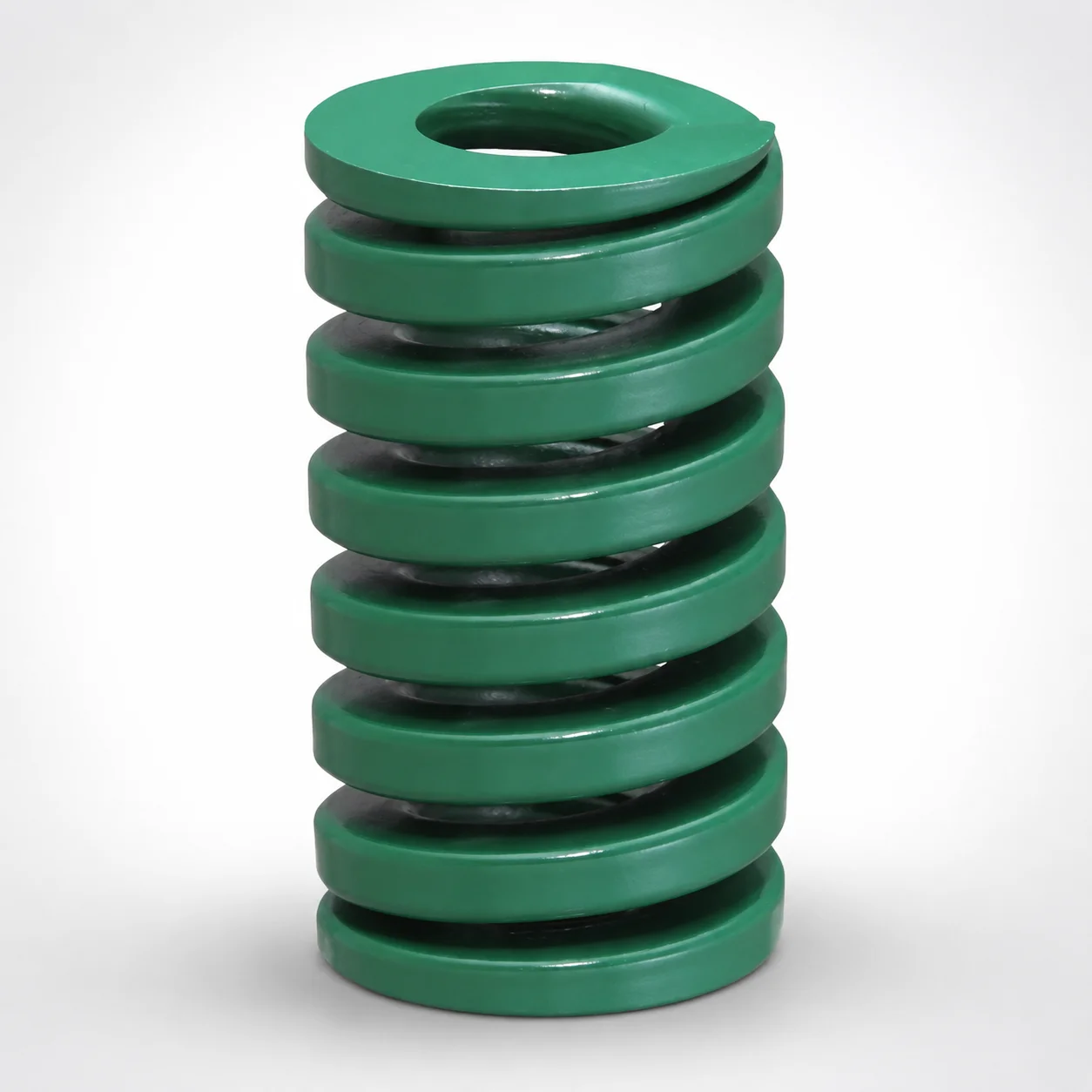
JIS Standard Heavy Duty Die Spring 24% Deflection
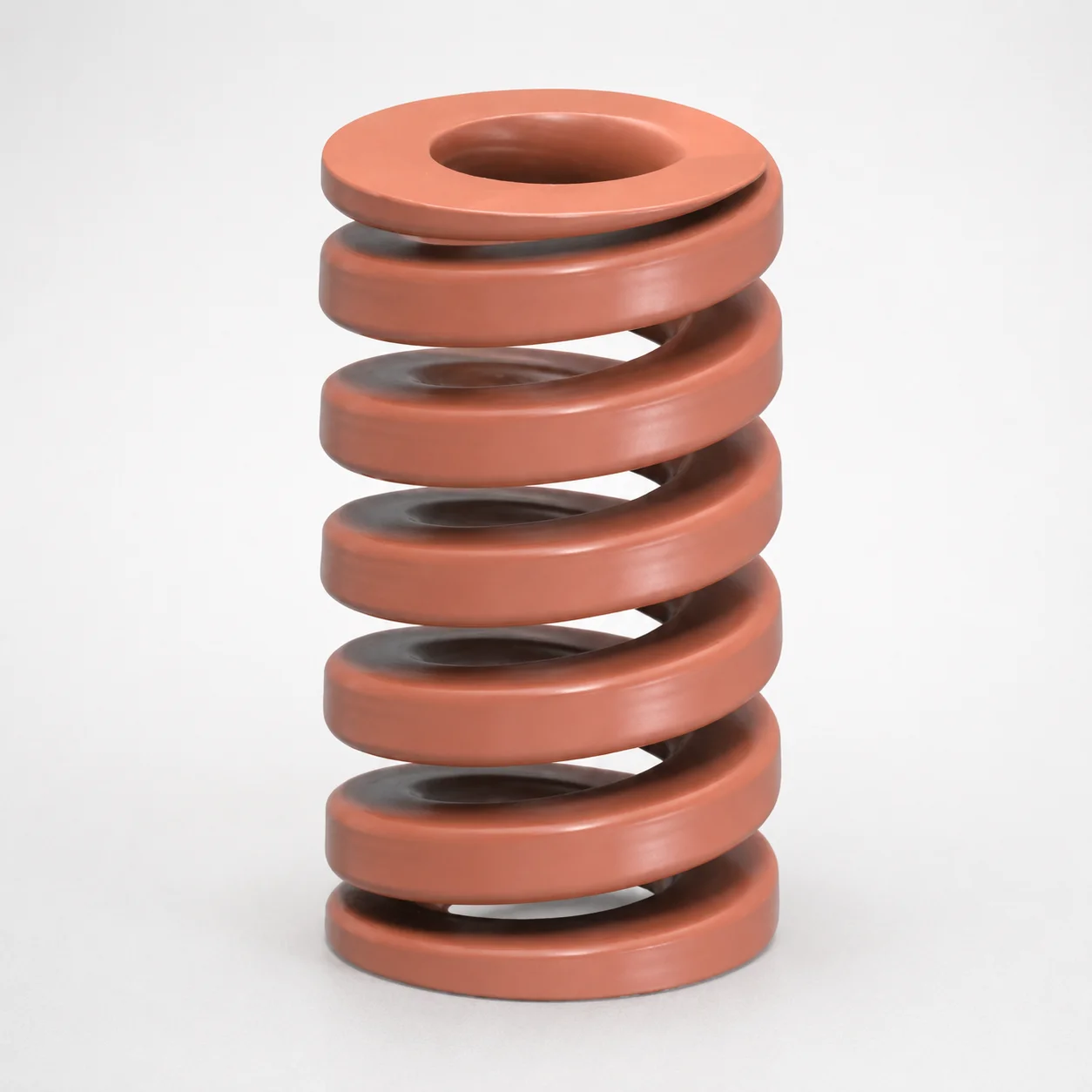
JIS Standard Chrome Silicon Oil-Tempered Wire Heavy Duty Die Spring 20% Deflection
Need Custom Specifications?
Our engineering team can help with custom configurations, material selection, and volume pricing.