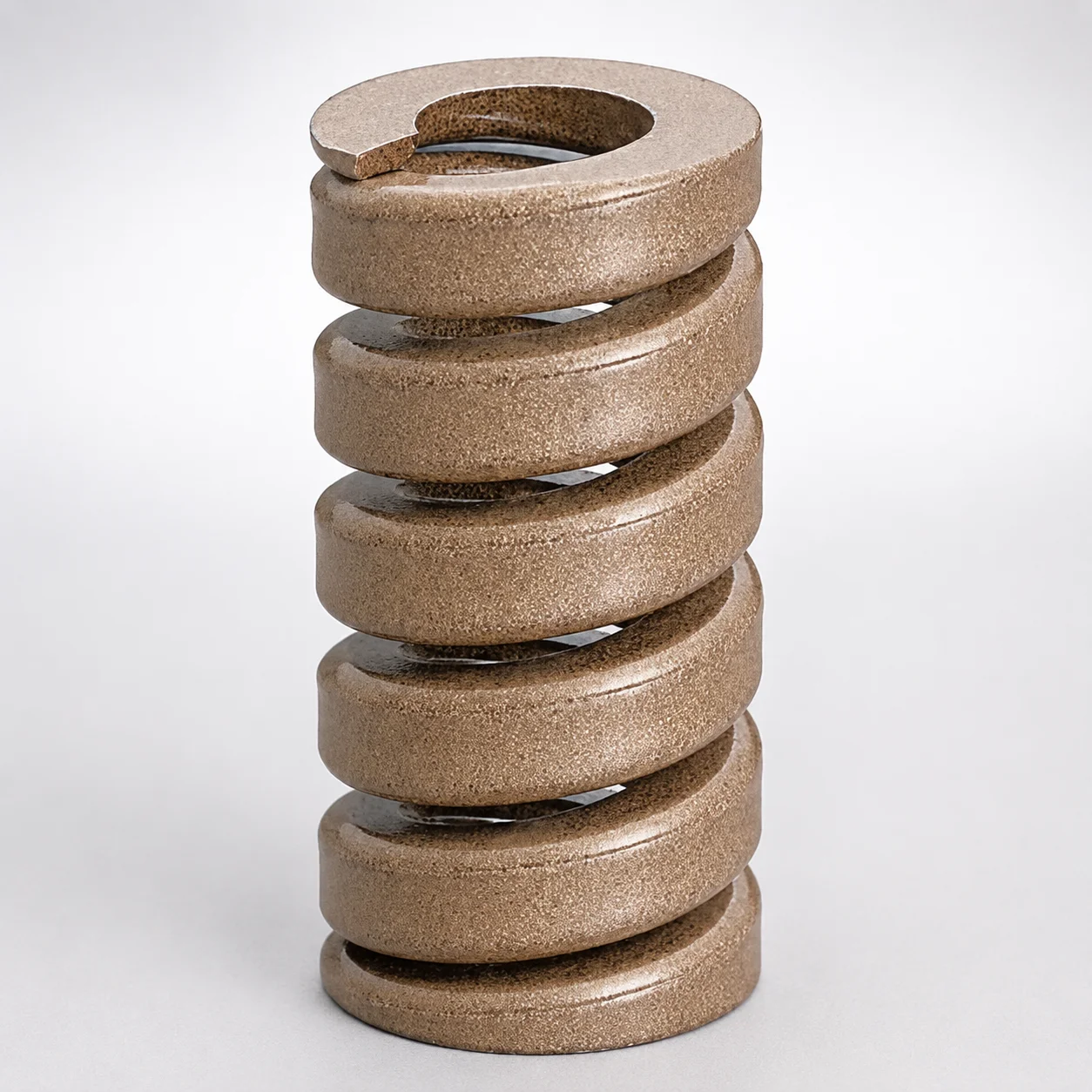
JIS Standard Heavy Duty Die Spring - 13% Deflection
Heavy Duty Die Spring - 13% Deflection is a Chrome Silicon spring designed for heavy-load die and press tooling, providing stable deflection behavior for consistent load control. The SWZ type suits demanding applications where spring reliability matters.
- 13% deflection ratio for controlled heavy-load response across press cycles
- Chrome Silicon steel construction supports dependable strength and fatigue resistance
- SWZ spring type built for heavy-duty tooling with wide load capability
- Compatible with JIS Standard tooling requirements for straightforward specification
Specifications
137 configurations available
| Maximum Load (N) | Outer Diameter D (mm) | Length L (mm) | type |
|---|---|---|---|
| 515 | 10 | 25 | - |
| 515 | 10 | 30 | - |
| 515 | 10 | 35 | - |
| 515 | 10 | 40 | - |
| 515 | 10 | 45 | - |
| 515 | 10 | 50 | - |
| 515 | 10 | 55 | - |
| 515 | 10 | 60 | - |
| 698 | 12 | 25 | - |
| 698 | 12 | 30 | - |
| 698 | 12 | 35 | - |
| 698 | 12 | 40 | - |
| 698 | 12 | 45 | - |
| 698 | 12 | 50 | - |
| 698 | 12 | 55 | - |
| 698 | 12 | 60 | - |
| 1191 | 14 | 30 | - |
| 1191 | 14 | 35 | - |
| 1191 | 14 | 40 | - |
| 1191 | 14 | 45 | - |
| 1191 | 14 | 50 | - |
| 1191 | 14 | 55 | - |
| 1191 | 14 | 60 | - |
| 1715 | 16 | 30 | - |
| 1715 | 16 | 35 | - |
| 1715 | 16 | 40 | - |
| 1715 | 16 | 45 | - |
| 1715 | 16 | 50 | - |
| 1715 | 16 | 55 | - |
| 1715 | 16 | 60 | - |
| 2157 | 18 | 30 | - |
| 2157 | 18 | 35 | - |
| 2157 | 18 | 40 | - |
| 2157 | 18 | 45 | - |
| 2157 | 18 | 50 | - |
| 2157 | 18 | 55 | - |
| 2157 | 18 | 60 | - |
| 2575 | 20 | 30 | - |
| 2575 | 20 | 35 | - |
| 2575 | 20 | 40 | - |
| 2575 | 20 | 45 | - |
| 2575 | 20 | 50 | - |
| 2575 | 20 | 55 | - |
| 2575 | 20 | 60 | - |
| 2575 | 20 | 65 | - |
| 2575 | 20 | 70 | - |
| 2575 | 20 | 75 | - |
| 2575 | 20 | 80 | - |
| 2575 | 20 | 90 | - |
| 2575 | 20 | 100 | - |
Product Guide
Application Scenarios+
This heavy-duty die spring is used in injection mold tooling to deliver predictable load and deflection in press-driven systems such as punch-and-die sets and die-height adjustment assemblies.
In automotive connector and terminal molds, where cycling loads can be high and repeated, the 13% deflection characteristic helps maintain stable load distribution for consistent clamp/actuation behavior. The spring’s Chrome Silicon construction supports long fatigue life under heavy-duty operating conditions.
- Punch/die sets: Use the spring to control return or contact force while managing load across repeated press cycles.
- Heavy press tooling: Select based on the specified maximum load range (515–16,045 N) to match the tooling force requirement.
- JIS-compliant mold builds: The JIS standard compatibility supports straightforward specification and interchangeability in standardized tooling documentation.
Material & Process Details+
This die spring is made from Chrome Silicon spring steel, selected for its balance of strength, elastic stability, and fatigue resistance—key properties for die and press tooling. The variant is specified for heavy loads up to 16,045 N, where durability under frequent cycling matters.
Typical production involves forming the wire into the required coil geometry, followed by heat treatment (commonly quench and temper or equivalent spring heat treatment) to achieve the spring’s designed elastic response and wear-free contact behavior.
- Heat treatment state: Spring-grade heat treated for stable deflection behavior (quench & temper class process).
- Hardness/toughness trade-off: Higher spring strength improves load capacity, while tempered toughness maintains resilience against fatigue cracking.
- Wear resistance: Optimized for cyclic loading; surface wear is not usually the limiting factor—fatigue life is.
Sizing & Selection Guide+
To choose the correct spring, match your die spring seat and force requirement to the spring’s specified ranges: maximum load 515–16,045 N, outer diameter D 10–50 mm, and length L 25–200 mm.
First, determine the required force in your mold’s compression/return system. Then select a spring whose maximum load comfortably exceeds the expected maximum tooling load with appropriate design margin.
- Outer diameter (D): Confirm the spring’s D fits within the available pocket/guide clearances without binding.
- Free length (L): Ensure the L range (25–200 mm) provides the intended working deflection stroke in the assembled stack-up.
- Fit and tolerances: When integrating into standardized JIS tooling interfaces, rely on the JIS spec compatibility; still verify seating flatness and guide alignment to prevent side loading during compression.
Frequently Asked Questions
How do I select a die spring using the 13% deflection rating for a press-driven mold system?+
What maximum load range is available for this JIS heavy duty die spring, and how should I apply it to my design margin?+
Which dimension should I prioritize when integrating this spring into a die-height adjustment or return stack?+
Is this spring suitable for heavy-duty injection mold tooling where fatigue life is a concern?+
Does the JIS standard compatibility affect how I specify the spring in my mold bill of materials?+
Related Products
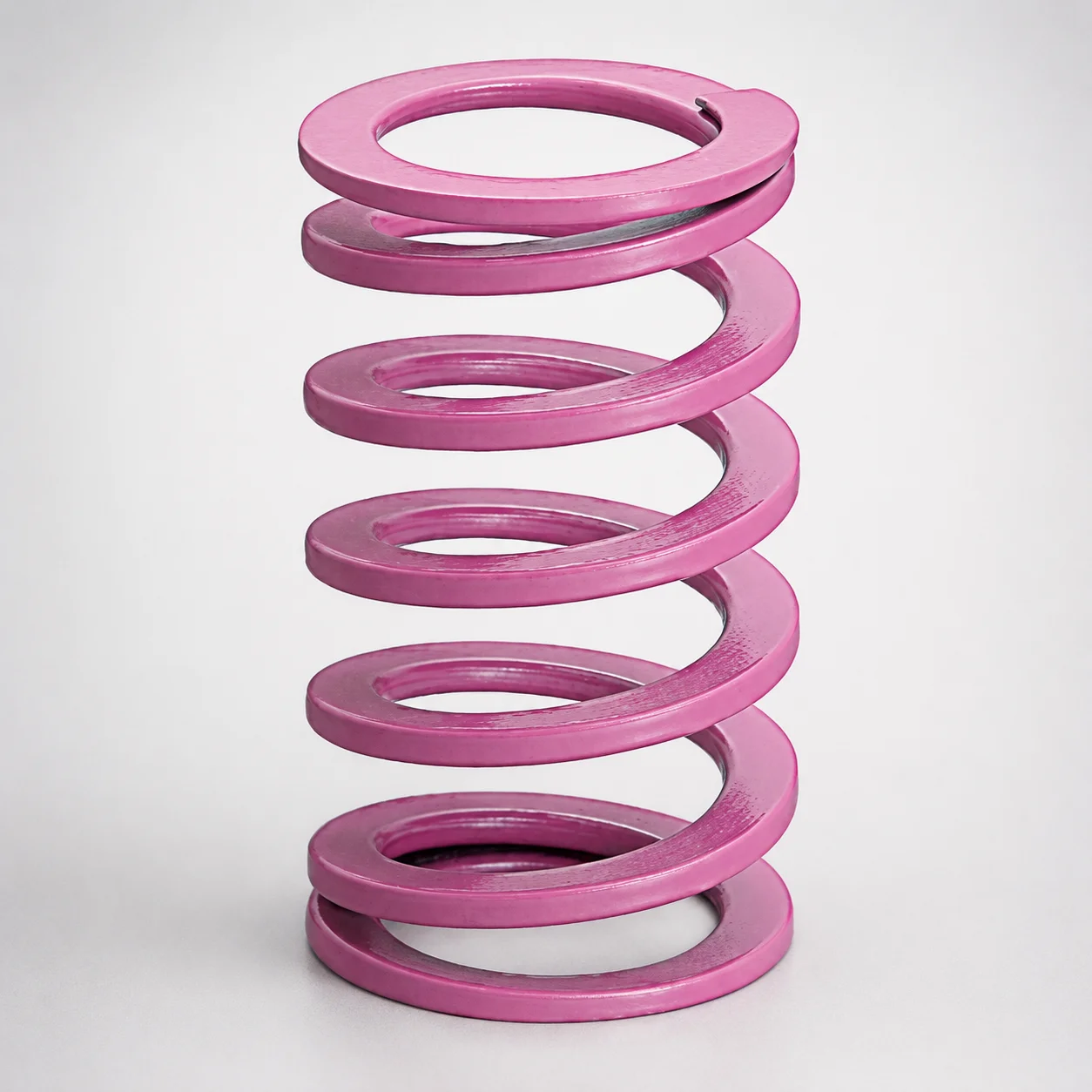
JIS Standard Chrome Silicon Medium Duty Die Spring 60% Deflection
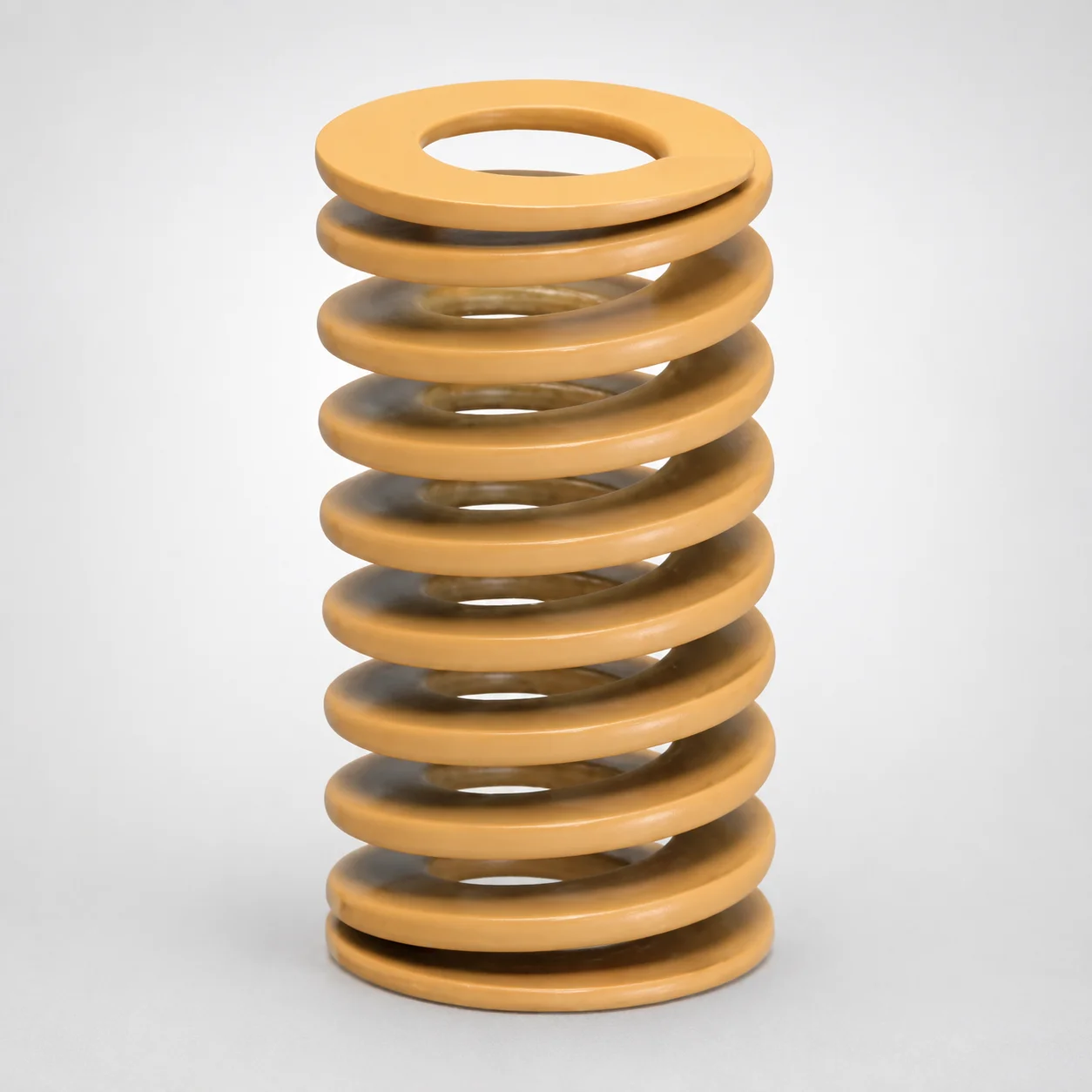
JIS Standard Chrome Silicon Medium Duty Die Spring - 50% Deflection
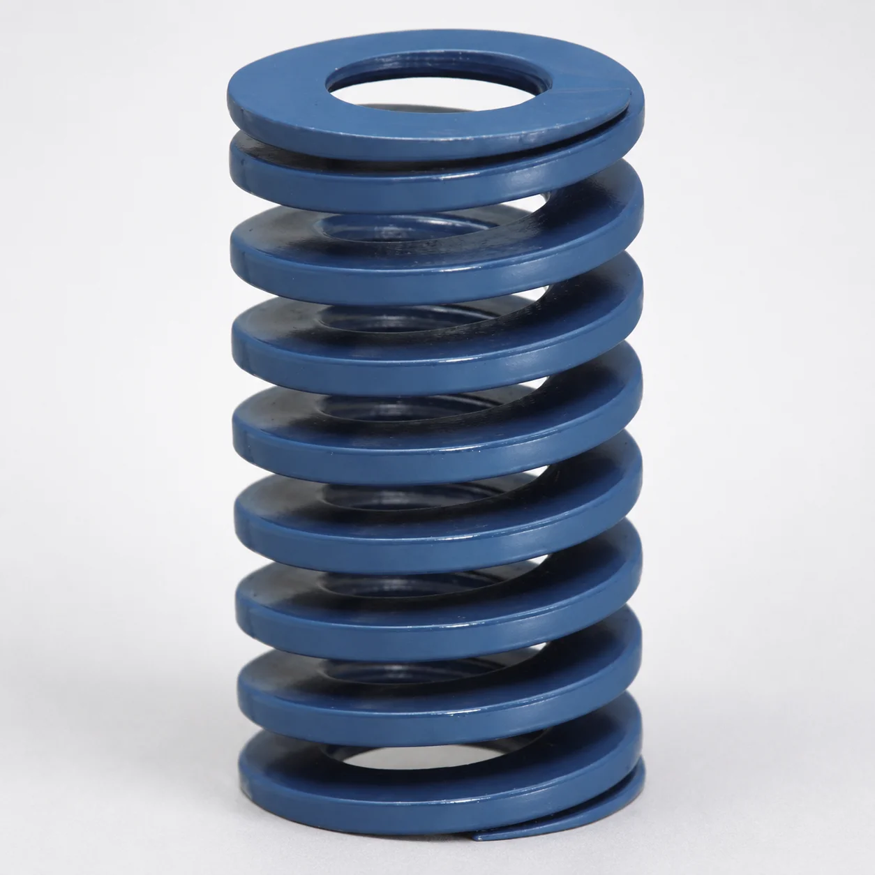
JIS Standard Chrome Silicon Steel Medium Duty Die Spring - 40% Deflection
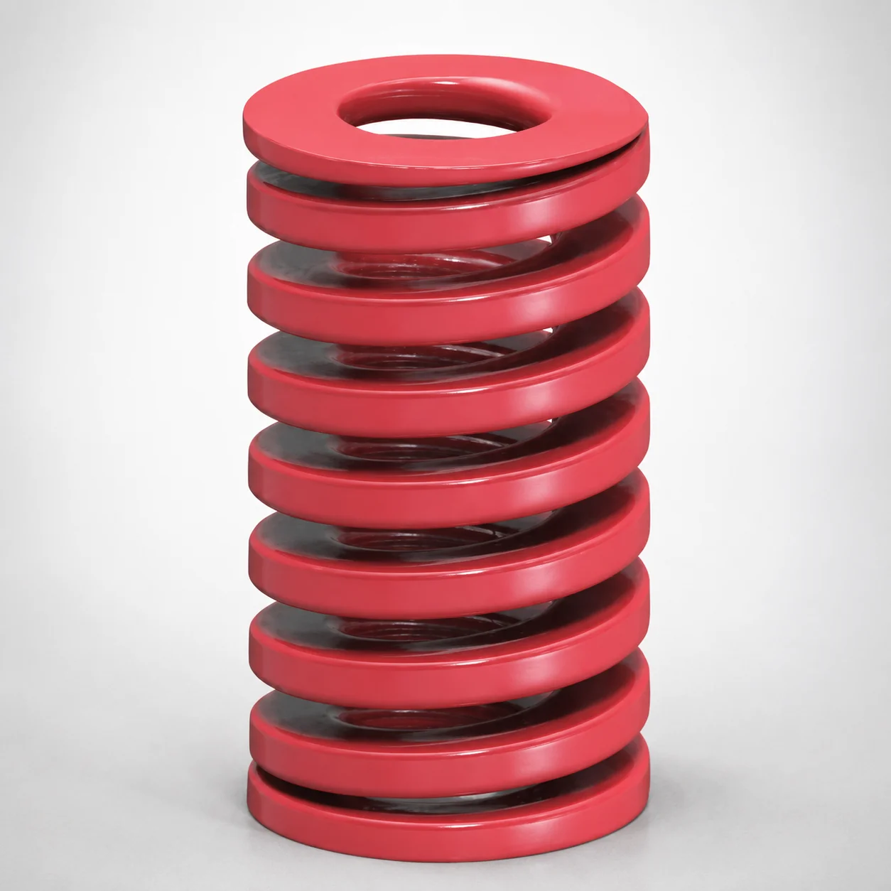
JIS Standard Medium Duty Die Spring 32% Deflection Chrome Silicon Coil Springs
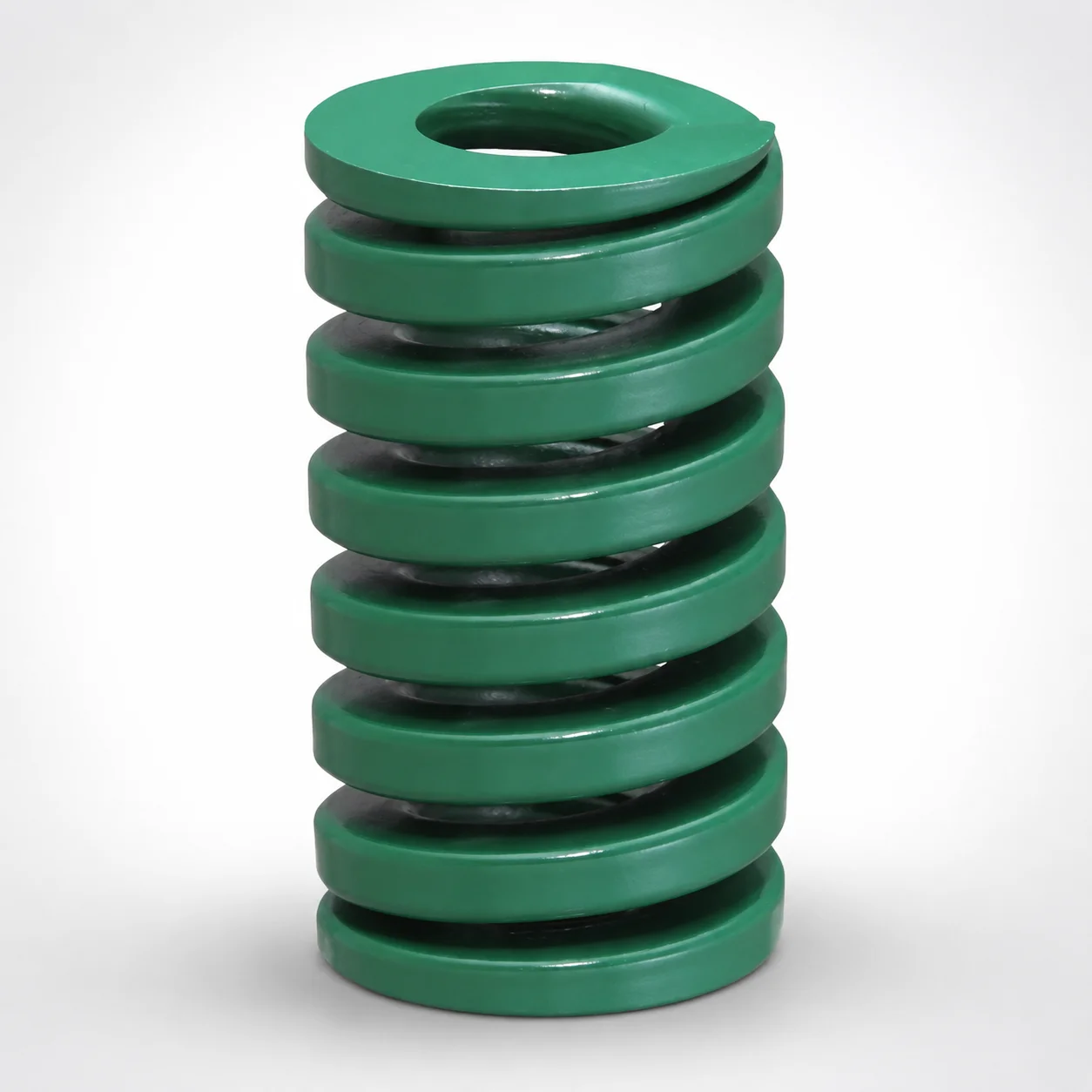
JIS Standard Heavy Duty Die Spring 24% Deflection
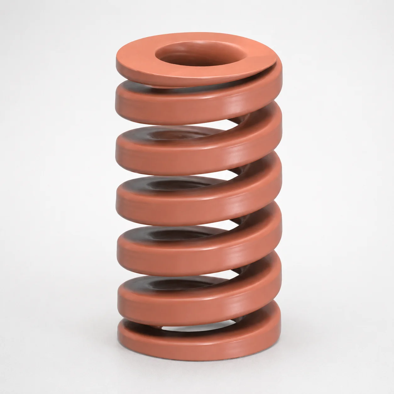
JIS Standard Chrome Silicon Oil-Tempered Wire Heavy Duty Die Spring 20% Deflection
Need Custom Specifications?
Our engineering team can help with custom configurations, material selection, and volume pricing.