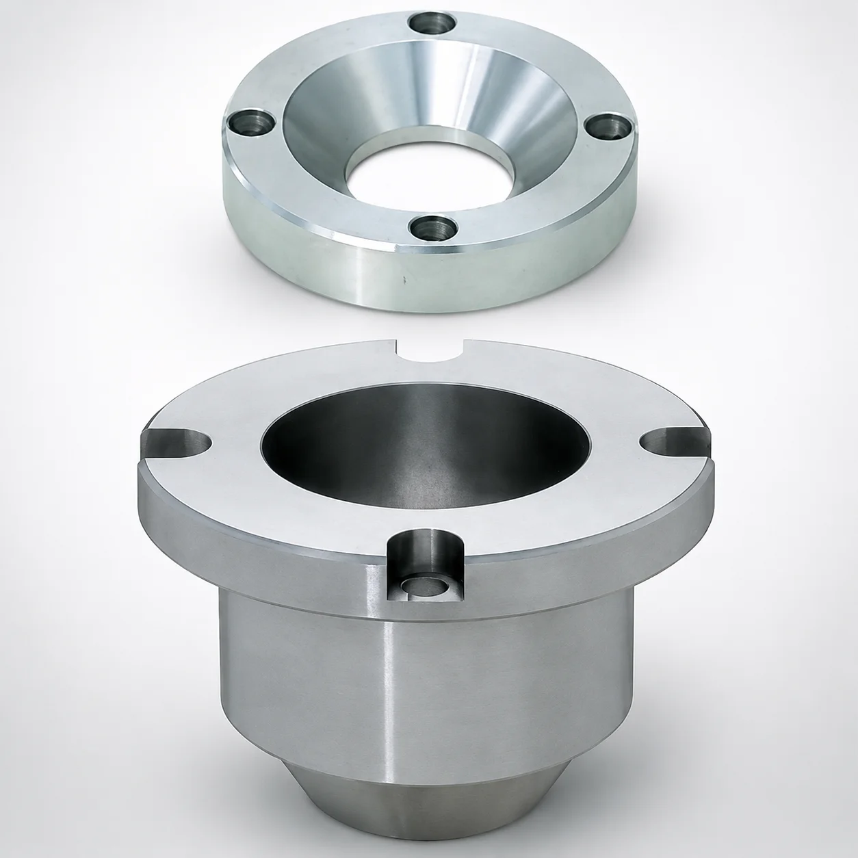
Sprue Bushings with Locate Ring for Extended Nozzle
Sprue Bushings with Locate Ring for Extended Nozzle (for tapered sprue tips) are designed to stabilize nozzle positioning and improve consistency in injection molding. The locating ring supports reliable setup when using extended nozzles and sprue systems.
- Extension sprue bushing with tapered tip for controlled mating with sprue nozzles
- Locate ring design helps maintain repeatable alignment during mold changeovers
- Supports normal nozzle touch geometry for predictable flow path connection
- Compatible with standard sprue bushing assemblies for high-availability production lines
Specifications
2 configurations available
| Material | A (Taper angle at sprue) (°) | L (L dimension) (mm) | P (Sprue diameter) (mm) | T (Locating ring height) (mm) | X (Sprue taper length) (mm) | type |
|---|---|---|---|---|---|---|
| SKD61 | 1 ~ 6 | 35 ~ 65 | 2.5 ~ 5 | 15 ~ 20 | 10 ~ 15 | - |
| HPM1 Equivalent | 1 ~ 6 | 35 ~ 65 | 2.5 ~ 5 | 15 ~ 20 | 10 ~ 15 | - |
Product Guide
Application Scenarios+
This extension sprue bushing is used in injection mold tooling where repeatable nozzle-to-sprue alignment is critical, especially when an extended nozzle is part of the gate or runner system. The tapered tip mates with tapered sprue nozzles, helping stabilize the connection and reduce variability in flow-path engagement.
- Automotive connector and housing molds: Use during production line changeovers to maintain consistent sprue pick-up with an extended nozzle length, improving part-to-part consistency in fill and weld-line behavior.
- Appliance and consumer product molds: The locating ring supports controlled setup, reducing misalignment risk during frequent tool cleaning and reinstallation.
- Industrial multi-cavity molds: Helps standardize nozzle touch geometry across cavities, supporting uniform gating performance in high-availability runs.
The locating ring height and the controlled taper geometry make this variant well-suited for stable alignment under repeated service conditions.
Material & Process Details+
The listed material for this sprue bushing option is SKD61, an H13-equivalent hot-work tool steel. SKD61 is chosen for its balanced hot strength, wear resistance, and toughness, which are important at the sprue/nozzle interface where thermal cycling and surface contact occur.
- Heat treatment: typically supplied in a hardened and tempered condition suitable for hot runner and sprue components (exact hardness is not specified in the provided data).
- Wear vs. toughness trade-off: higher hardness improves resistance to fretting and abrasive wear at the tapered mating surfaces, while tempered toughness helps prevent chipping under contact loads.
- Alternative grade: the listing also references HPM1 equivalent. In practice, selection between these grades is made based on target wear/impact behavior for the mold’s thermal and mechanical duty cycle; confirm hardness after heat treatment to match your design requirement.
Sizing & Selection Guide+
Select the bushing geometry by matching the sprue taper and nozzle diameter engagement to your mold’s nozzle touch design and the sprue bushing assembly layout. The key controlled dimensions provided are:
- A (taper angle at sprue): 1 ~ 6°
- X (sprue taper length): 10 ~ 15 mm
- P (sprue diameter): 2.5 ~ 5 mm
- L (overall length): 35 ~ 65 mm
- T (locating ring height): 15 ~ 20 mm
Start by choosing the taper angle A, then ensure the nozzle mating length aligns with X to achieve full contact across the intended taper zone. Verify the sprue diameter P matches the nozzle/sprue bore size to maintain consistent melt entry. Use L to control reach for extended nozzle support, and use T to ensure the locating ring seats correctly in the mating cavity/core feature, improving alignment during reinstallation.
Tolerance note: No tolerance values are provided in the data, so confirm drawing tolerances and fit type (slip/locating) in your assembly plan to avoid excessive interference or clearance.
Frequently Asked Questions
How do I choose the correct taper angle (A) and taper length (X) for stable nozzle-to-sprue alignment?+
What sprue diameter (P) range is compatible with this extension sprue bushing?+
How does the locating ring height (T) affect mold changeover repeatability for extended nozzles?+
When should I consider SKD61 versus the listed HPM1-equivalent option for sprue bushing service?+
How do I select the correct overall length (L) for nozzle support in an extended nozzle sprue system?+
Related Products
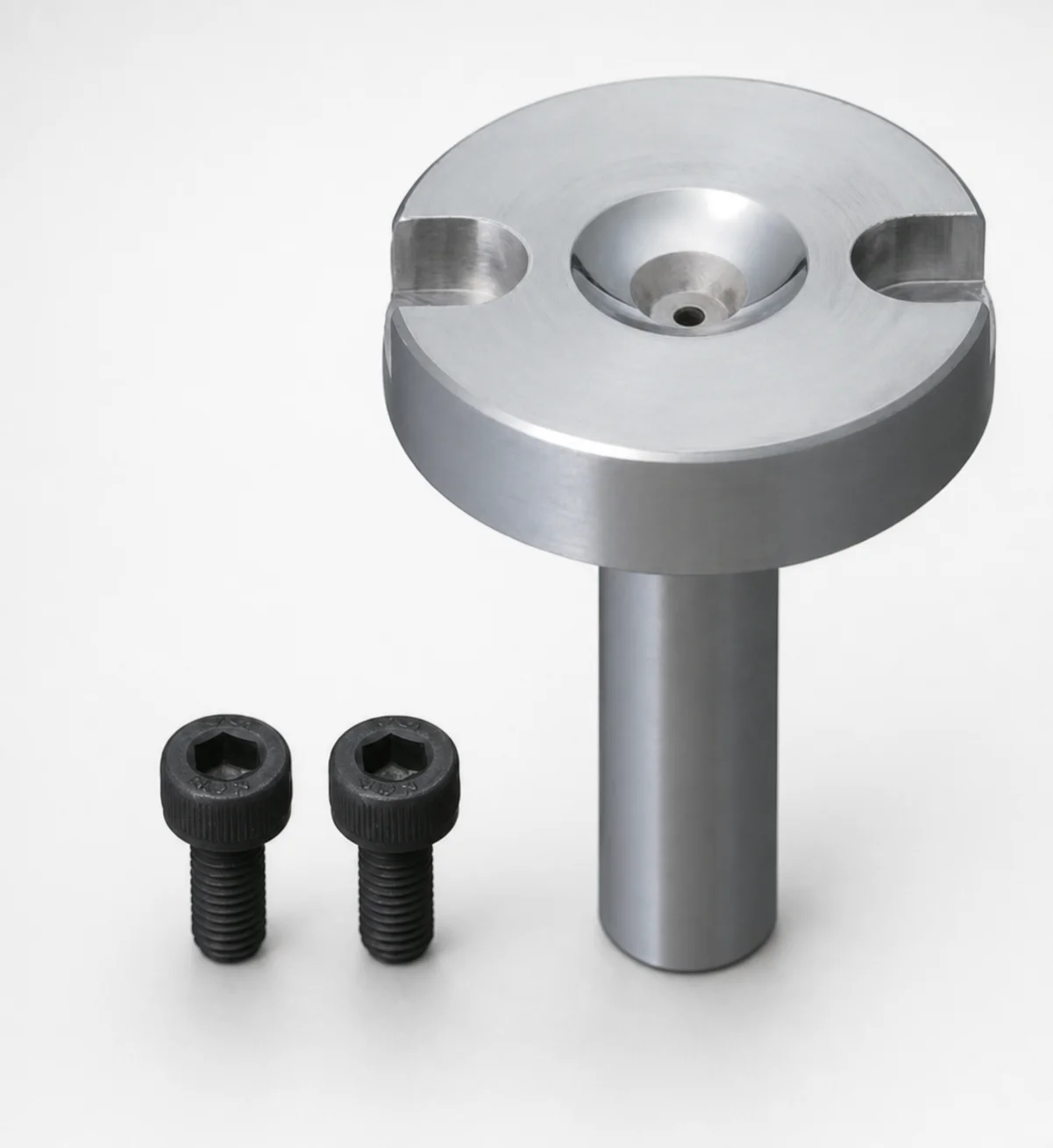
Bolt Fixing Sprue Bushings - Flange Thickness 10 mm
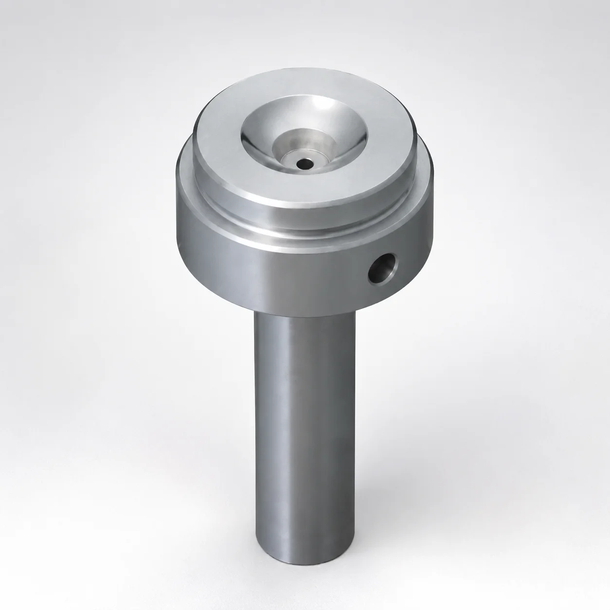
Sprue Bushings Shoulder Type - Flange Thickness 15 mm
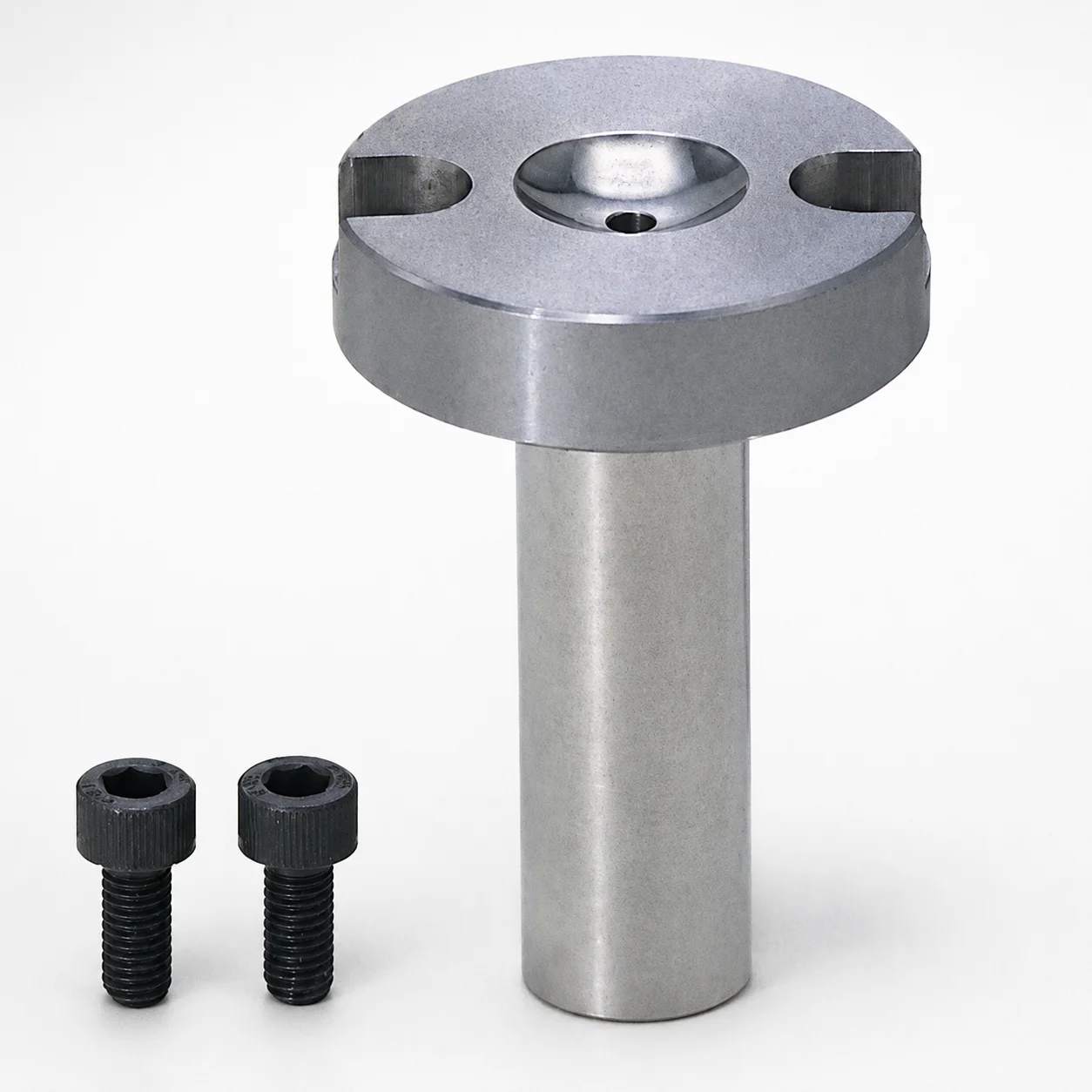
Sprue Bushings - Bolt Fixing Flange Thickness 10 mm
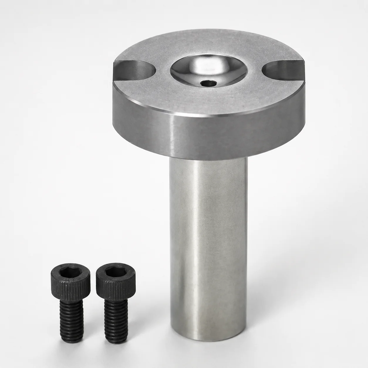
Sprue Bushings - Bolt Fixing, Flange Thickness 10 mm
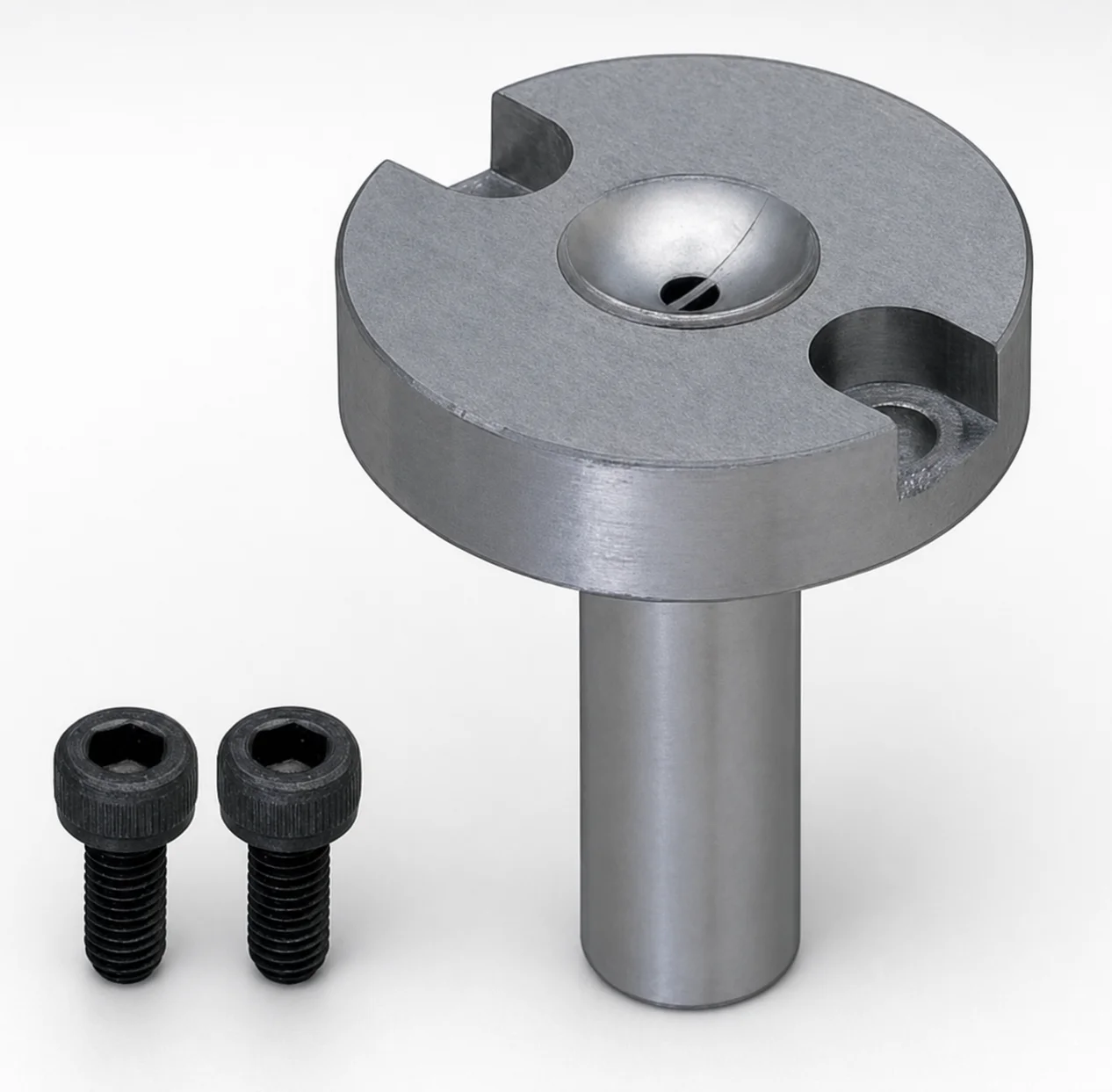
JIS Standard Steel Sprue Bushings - Bolt Fixing String Eliminator (Flange 10 mm)
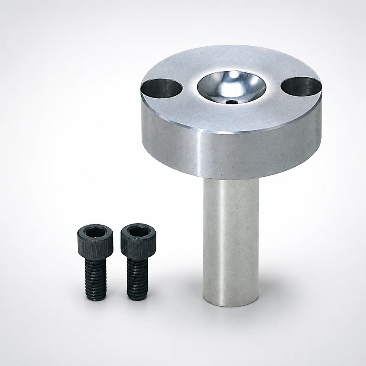
Sprue Bushings - Bolt Fixing Flange Thickness 15 mm
Need Custom Specifications?
Our engineering team can help with custom configurations, material selection, and volume pricing.