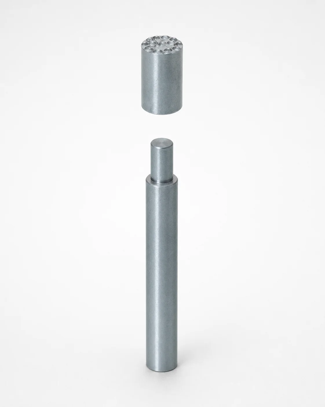
SKD61 Steel Date Marked Pins for Die Casting
Date marked pins for die casting (SKD61 steel) are press-fit inserts engineered to produce clear year/date engraving on cast dies. The flange stopper mounting improves positional stability and supports smooth, repeatable production.
- Flange stopper design helps lock the insert position during press-fit installation
- SKD61 steel construction supports wear resistance in continuous die casting
- Consistent engraving accuracy for readable date markings on large cast dies
- Used for production dies needing reliable year information marking
Specifications
12 configurations available
| D (Shaft Diameter) (mm) | L (L dimension) (mm) | type |
|---|---|---|
| 8 | - | - |
| 10 | - | - |
| 12 | - | - |
| 8 | - | - |
| 10 | - | - |
| 12 | - | - |
| 8 | 30 ~ 100 | - |
| 10 | 30 ~ 100 | - |
| 12 | 30 ~ 100 | - |
| 8 | 30 ~ 100 | - |
| 10 | 30 ~ 100 | - |
| 12 | 30 ~ 100 | - |
Product Guide
Application Scenarios+
These date marked pins are designed for die casting tooling, where consistent, readable year/date engraving must be maintained across long production runs. Installed as press-fit inserts with a flange stopper mount, they help maintain stable positioning during assembly and subsequent thermal cycles.
In large automotive die casting, they are commonly used on tooling sets that require traceable production dates on cast components or die areas. The flange stopper assists with repeatable location, improving engraving legibility despite vibration and handling.
- Die/component traceability markings: year/date engraving that must remain clear for QA and audit workflows.
- Stable mounting in large molds: the flange stopper limits insert drift during press-fit installation.
- Continuous die casting environments: SKD61 steel supports wear resistance where pins experience contact and rubbing near engraved features.
Material & Process Details+
This product is made from SKD61, a chromium-molybdenum-vanadium hot-work tool steel commonly used for high-load die casting components. In practice, SKD61 is frequently treated as equivalent to AISI H13-class hot-work tooling steel for heat-treat planning.
For durability, the typical balance targets high wear resistance while retaining toughness to survive repeated heating/cooling. If pins are quenched and tempered, hardness is usually set in the range of about 48–52 HRC (process-dependent), improving resistance to abrasion at the engraving interface.
- Wear vs. toughness trade-off: higher hardness improves abrasion resistance but can reduce impact toughness.
- Heat treatment state: quenched & tempered condition is standard; nitriding is optional in specialized cases where surface hardness is prioritized.
When comparing alternatives, SKD61-class steels are generally preferred over lower-alloy tool steels because they better withstand hot-working conditions and cyclical thermal stress.
Sizing & Selection Guide+
Selection starts with the shaft diameter (D) and the fixed length (L). This series is available with D = 8, 10, or 12 mm, while L is fixed at 30 to 100 mm.
To match your mold cavity/core requirements, choose the pin diameter based on the diameter of the mating press-fit hole or boss in the die component. Then select the L dimension to provide the required projection and seating depth so the flange stopper bears against the intended reference surface.
- Fit considerations: press-fit performance depends on interference; follow your press-fit tolerance band for the D selection to prevent loosening or excessive insertion stress.
- Engraving alignment: stable seating from the flange stopper mount helps preserve the year/date position during assembly.
- Fixed vs. configurable: L is provided as a fixed range (30–100 mm), and D is the configurable size option (8/10/12 mm).
Verify that your groove/engraving feature clearance accommodates the selected shaft diameter without contacting nearby die steel surfaces during thermal expansion.
Frequently Asked Questions
Which shaft diameter options are available for SKD61 date marked pins?+
This series is available with D (shaft diameter) = 8, 10, or 12 mm. Selecting the correct D is critical for press-fit hole interference in the die steel.
What length range can be selected for die casting flange stopper date marked pins?+
The L (length) dimension is specified as 30 to 100 mm for this series. Choose L to achieve the required seating depth and proper projection while the flange stopper contacts the reference surface.
Why use SKD61 steel for date engraving inserts in die casting tooling?+
SKD61 is a hot-work tool steel class (often compared to AISI H13) used for die casting components where wear resistance and thermal cycling durability matter. For press-fit date marking features, it helps maintain engraving performance by resisting abrasion at contact zones.
How does the flange stopper mount affect install stability?+
The flange stopper is intended to improve positional stability during press-fit installation. By providing a physical stop surface, it reduces insert drift so the year/date engraving remains aligned through handling and production thermal cycles.
What tolerance and fit approach should be used when matching press-fit holes to pin diameter (D)?+
Because the pins are press-fit inserts, the interference depends on your mating hole diameter for the chosen D = 8/10/12 mm. Use your standard press-fit tolerance band for die steel to avoid loosening (insufficient interference) or excessive stresses (too much interference) during assembly.
Related Products
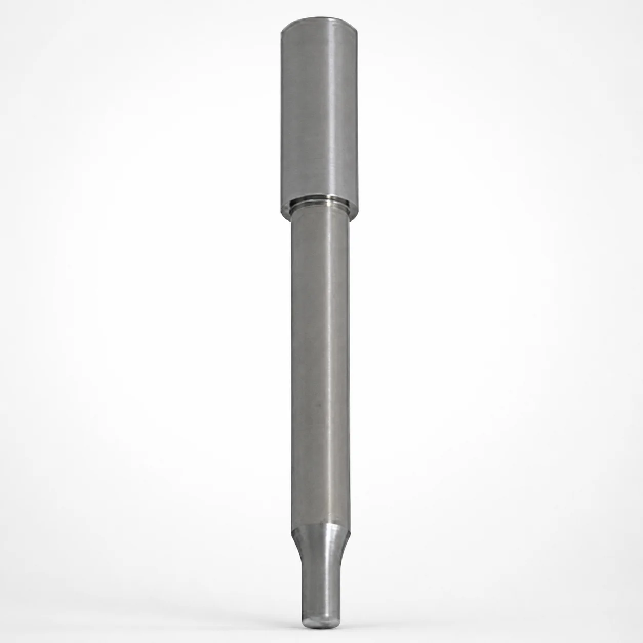
TiCN Option Powder High Speed Steel Round Stopper Punches Single-Stepped
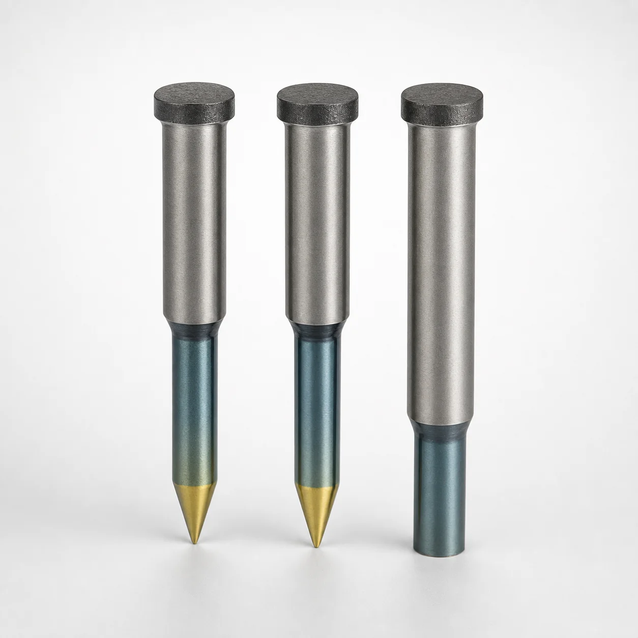
Powdered High-Speed Steel Round Stopper Punches Single-Stepped
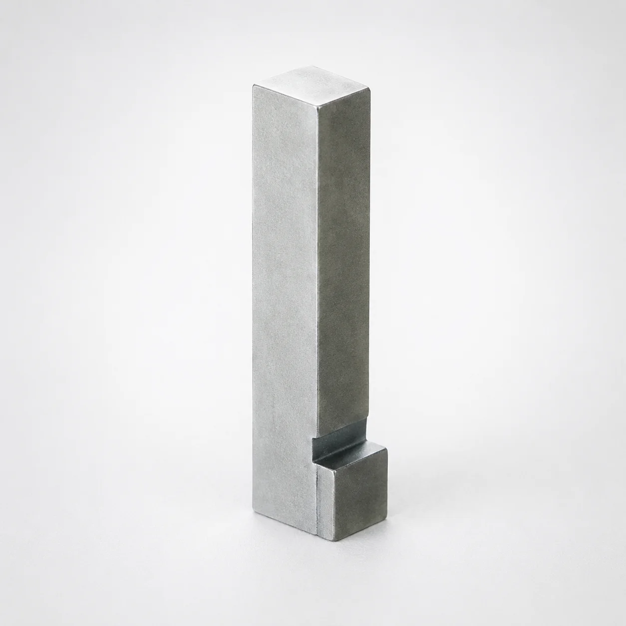
JIS Standard Steel Block Core Pins No Tip No Engraving
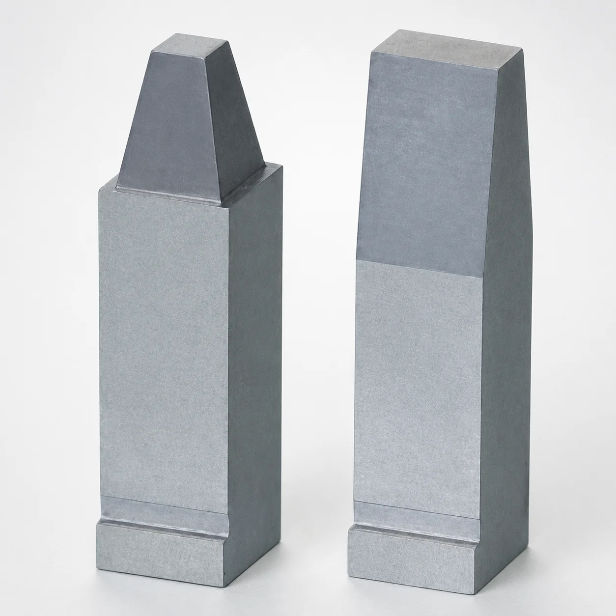
Steel Block Core Pins No-Tip with Flange
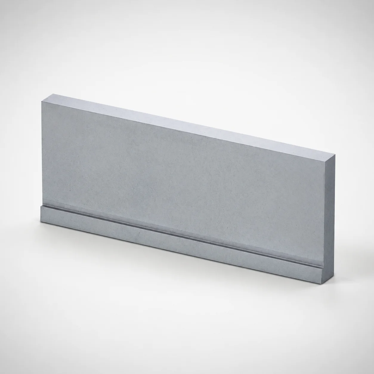
Block Core Pins No Tip Processing With Flange
JST PTFE Pipe Thread Seal Tapes
Need Custom Specifications?
Our engineering team can help with custom configurations, material selection, and volume pricing.