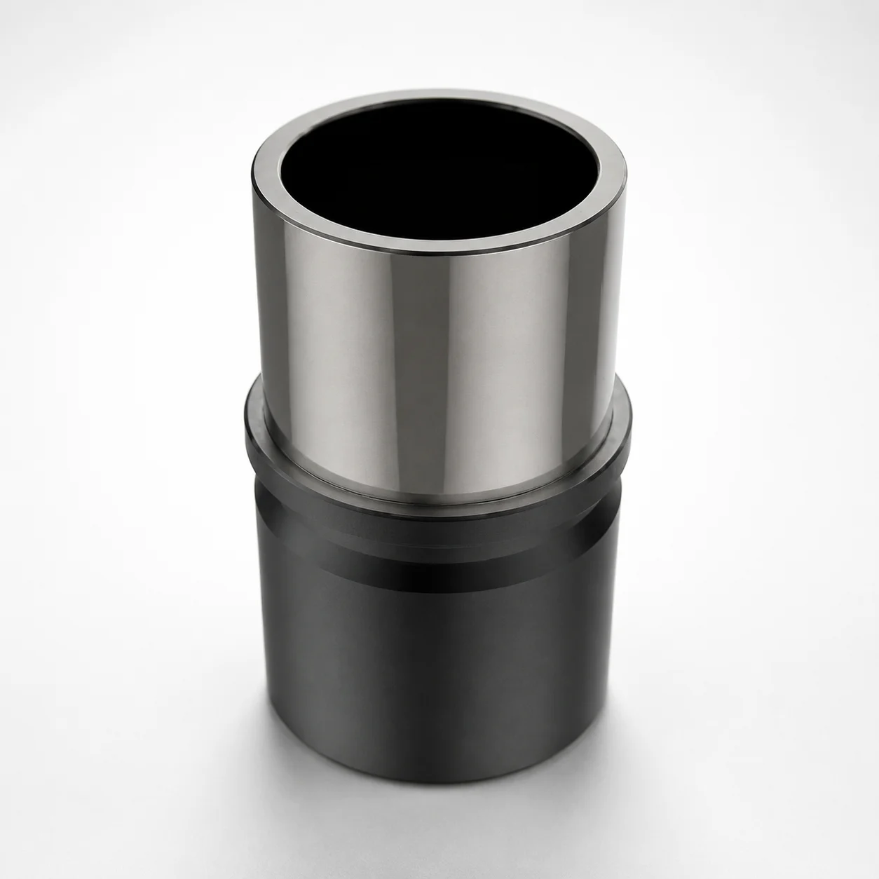
ISO 9448-7 1.3505 Steel Guide Bushings for Ball Cages
Guide Bushings for Ball Cages (1.3505 steel) are manufactured to ISO 9448-7 to support reliable ball cage guidance in industrial die and bearing assemblies. Heat treatment to 60–64 HRC helps maintain dimensional stability under load.
- Compliant ISO 9448-7 design for consistent guide performance
- Rolling bearing steel construction with 60–64 HRC hardness
- Optional DFC retaining clamp for secure mounting retention
- Used for ball cage guide systems where precise alignment is critical
Specifications
110 configurations available
| Length L (mm) | D (Pillar outer diameter) (mm) | Alteration |
|---|---|---|
| 35 | 19 | Without DFC Retaining Clamp |
| 35 | 19 | With DFC Retaining Clamp |
| 43 | 19 | Without DFC Retaining Clamp |
| 43 | 19 | With DFC Retaining Clamp |
| 59 | 19 | Without DFC Retaining Clamp |
| 59 | 19 | With DFC Retaining Clamp |
| 35 | 20 | Without DFC Retaining Clamp |
| 35 | 20 | With DFC Retaining Clamp |
| 43 | 20 | Without DFC Retaining Clamp |
| 43 | 20 | With DFC Retaining Clamp |
| 59 | 20 | Without DFC Retaining Clamp |
| 59 | 20 | With DFC Retaining Clamp |
| 35 | 24 | Without DFC Retaining Clamp |
| 35 | 24 | With DFC Retaining Clamp |
| 55 | 24 | Without DFC Retaining Clamp |
| 55 | 24 | With DFC Retaining Clamp |
| 59 | 24 | Without DFC Retaining Clamp |
| 59 | 24 | With DFC Retaining Clamp |
| 79 | 24 | Without DFC Retaining Clamp |
| 79 | 24 | With DFC Retaining Clamp |
| 80 | 24 | Without DFC Retaining Clamp |
| 80 | 24 | With DFC Retaining Clamp |
| 35 | 25 | Without DFC Retaining Clamp |
| 35 | 25 | With DFC Retaining Clamp |
| 55 | 25 | Without DFC Retaining Clamp |
| 55 | 25 | With DFC Retaining Clamp |
| 59 | 25 | Without DFC Retaining Clamp |
| 59 | 25 | With DFC Retaining Clamp |
| 79 | 25 | Without DFC Retaining Clamp |
| 79 | 25 | With DFC Retaining Clamp |
| 80 | 25 | Without DFC Retaining Clamp |
| 80 | 25 | With DFC Retaining Clamp |
| 42 | 30 | Without DFC Retaining Clamp |
| 42 | 30 | With DFC Retaining Clamp |
| 69 | 30 | Without DFC Retaining Clamp |
| 69 | 30 | With DFC Retaining Clamp |
| 75 | 30 | Without DFC Retaining Clamp |
| 75 | 30 | With DFC Retaining Clamp |
| 93 | 30 | Without DFC Retaining Clamp |
| 93 | 30 | With DFC Retaining Clamp |
| 93 | 30 | Without DFC Retaining Clamp |
| 93L | 30 | With DFC Retaining Clamp |
| 42 | 32 | Without DFC Retaining Clamp |
| 42 | 32 | With DFC Retaining Clamp |
| 69 | 32 | Without DFC Retaining Clamp |
| 69 | 32 | With DFC Retaining Clamp |
| 75 | 32 | Without DFC Retaining Clamp |
| 75 | 32 | With DFC Retaining Clamp |
| 93 | 32 | Without DFC Retaining Clamp |
| 93 | 32 | With DFC Retaining Clamp |
Product Guide
Application Scenarios+
These ISO 9448-7 guide bushings are used in ball cage guidance systems inside industrial bearing assemblies and die-related mechanical interfaces where controlled rolling alignment is required. In practice, they help maintain cage concentricity while the mold or actuator experiences repeated motion, vibration, and changing loads.
They are commonly specified for large die-casting and heavy-duty tooling that uses ball cage mechanisms for smooth part movement, because the guide bushing’s defined collar fit supports stable alignment over time. The 1.3505 steel construction and 60–64 HRC heat treatment are suited to resist wear from cage contact and to reduce dimensional drift under load.
- Die-casting bearing housings: supports consistent rolling alignment during cyclic operations.
- Ball cage guide systems: improves repeatability by stabilizing the guide geometry.
- Mounting with retention clamp (optional): the DFC variant supports secure assembly retention where vibration is expected.
Material & Process Details+
The bushing is made from 1.3505 (rolling bearing steel) and manufactured to ISO 9448-7. The steel is heat treated to 60–64 HRC, which balances wear resistance against toughness for guide applications where sliding/rolling contact and localized stress occur.
At this hardness level, the component is designed to maintain alignment by limiting surface wear and reducing the tendency for micro-deformation under guide loads. The tighter hardness range (60–64 HRC) helps provide consistent performance across batches.
- Hardness: 60–64 HRC for stable guide behavior under repeated contact.
- Wear vs. toughness: higher hardness increases wear resistance, but requires correct handling to avoid shock loading.
- Manufacturing/process: produced to ISO 9448-7 with heat treatment to the specified hardness band (state as provided).
No alternative steel grades are specified in the provided data; selection should therefore be based on the required hardness and ISO 9448-7 geometry.
Sizing & Selection Guide+
Select the guide bushing by matching the length L and the pillar outer diameter D to the corresponding mold/assembly features of your ball cage guide system. This series supports L = 35–150 mm and D = 19–80 mm; choose the closest available size that fits the cavity/core interface and the cage guide space.
- Step 1: Determine the required axial guidance length, then select L within 35–150 mm to cover the full contact/support zone.
- Step 2: Measure the pillar outer diameter requirement and select D within 19–80 mm to ensure the correct collar fit for guidance.
- Step 3: Confirm the variant for retention—either without DFC retaining clamp or with DFC retaining clamp—based on whether your assembly needs extra mounting retention under vibration.
Because the input data does not provide tolerance values, engineers should verify fit to their drawing requirements (e.g., press-fit/clearance intent) during final design review.
Frequently Asked Questions
What ISO 9448-7 alignment features should I expect from this guide bushing in a ball cage system?+
Is the specified hardness (60–64 HRC) appropriate for heavy-load die-casting tooling guide contact?+
When should I choose the version with the DFC retaining clamp versus the one without?+
How do I determine the correct bushing size for my existing pillar interface?+
Related Products
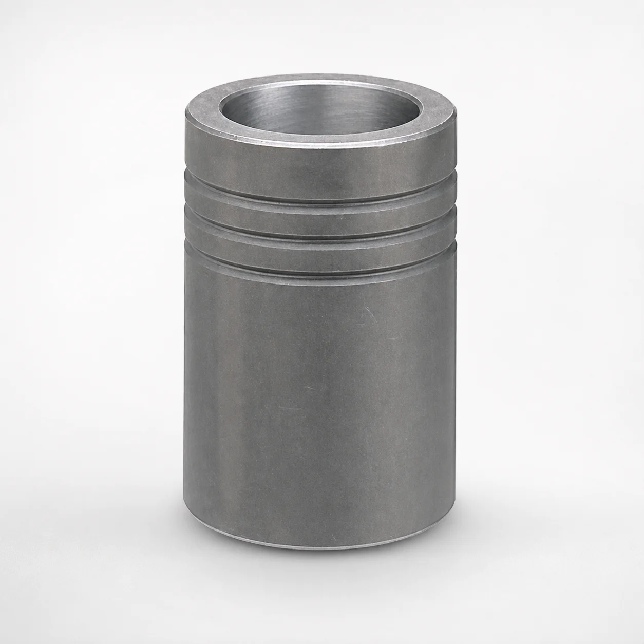
MBB Ball Guide Bushings for Die Sets Bonded by Devcon Adhesive
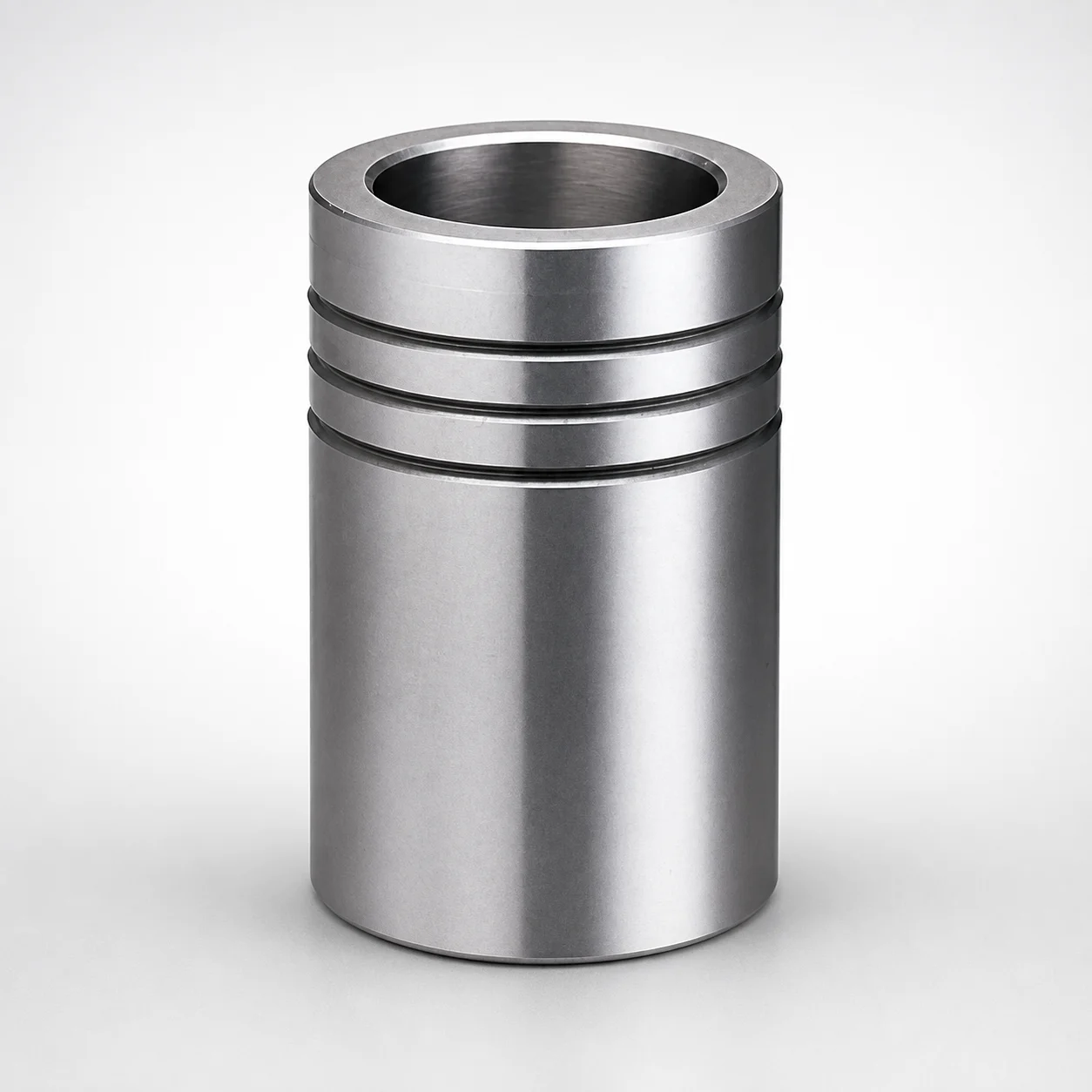
Ball Guide Bushings for Die Sets
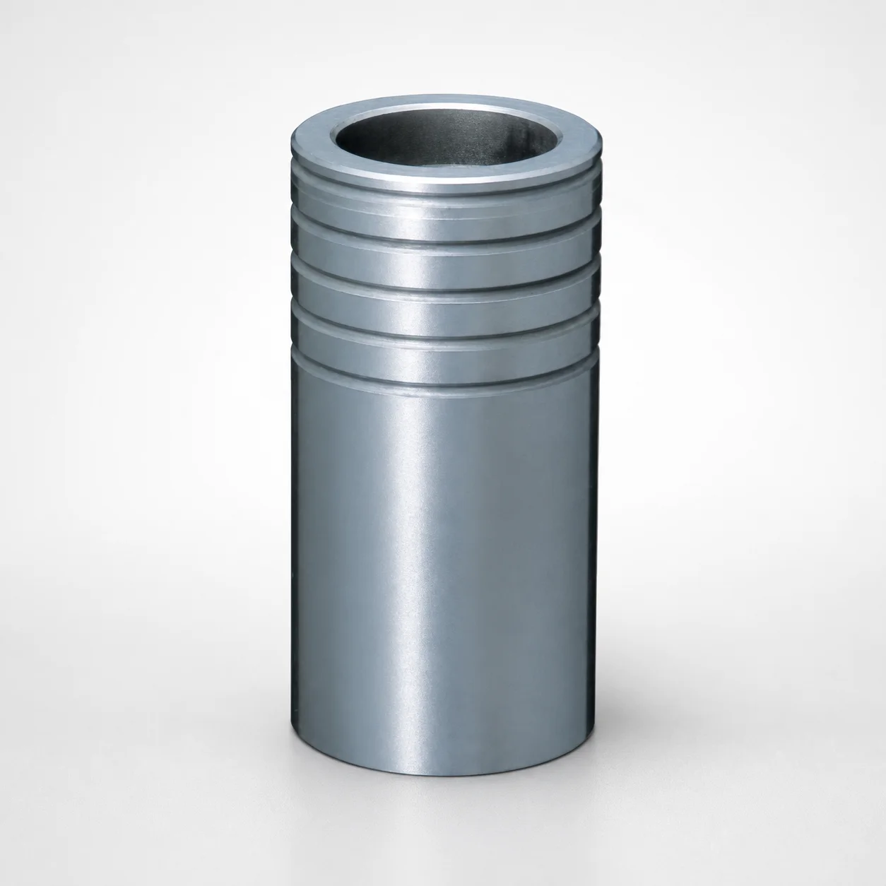
Ball Guide Bushings for Die Sets - Loctite Adhesive LBB Type
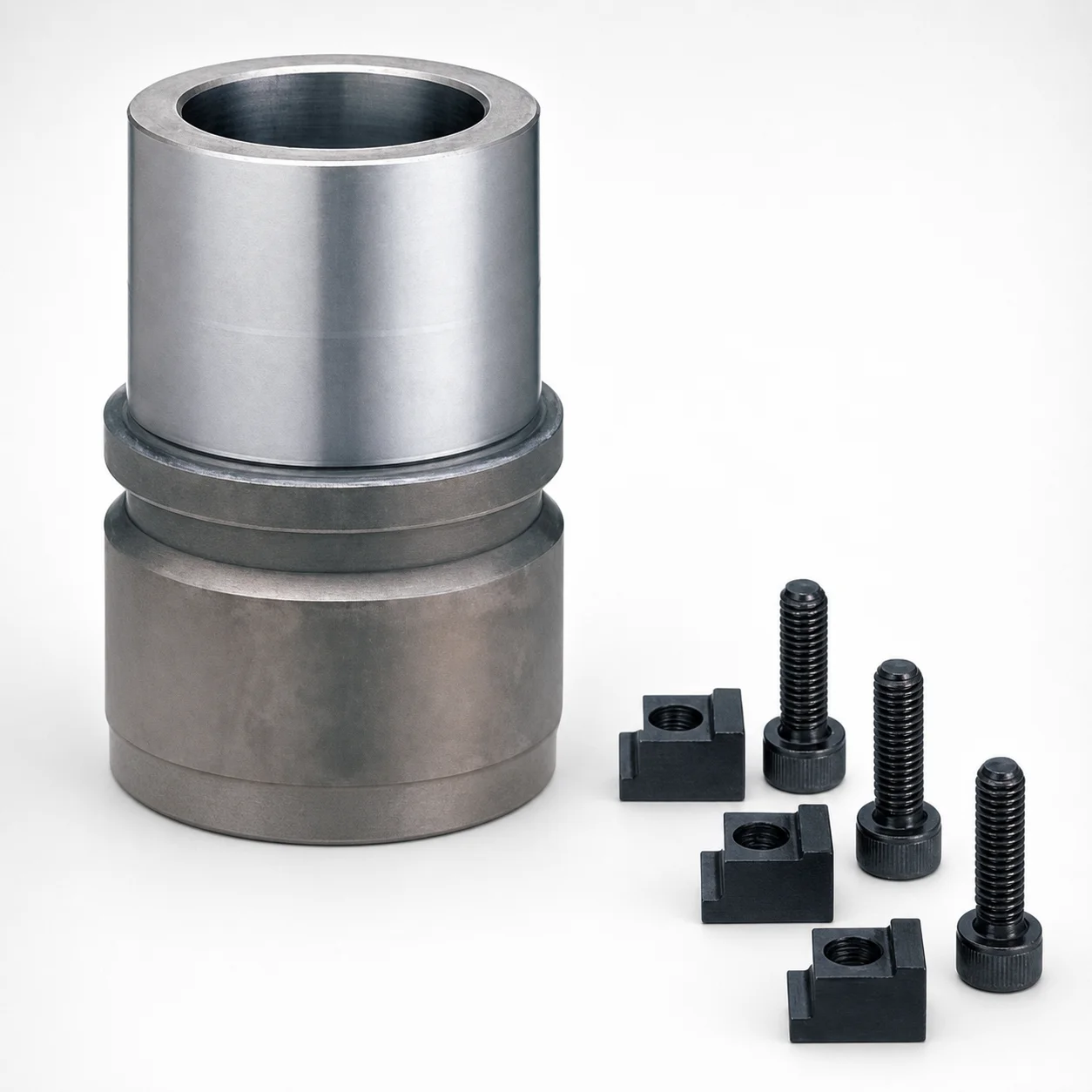
RBB Ball Guide Bushings for Die Sets - Detachable Type
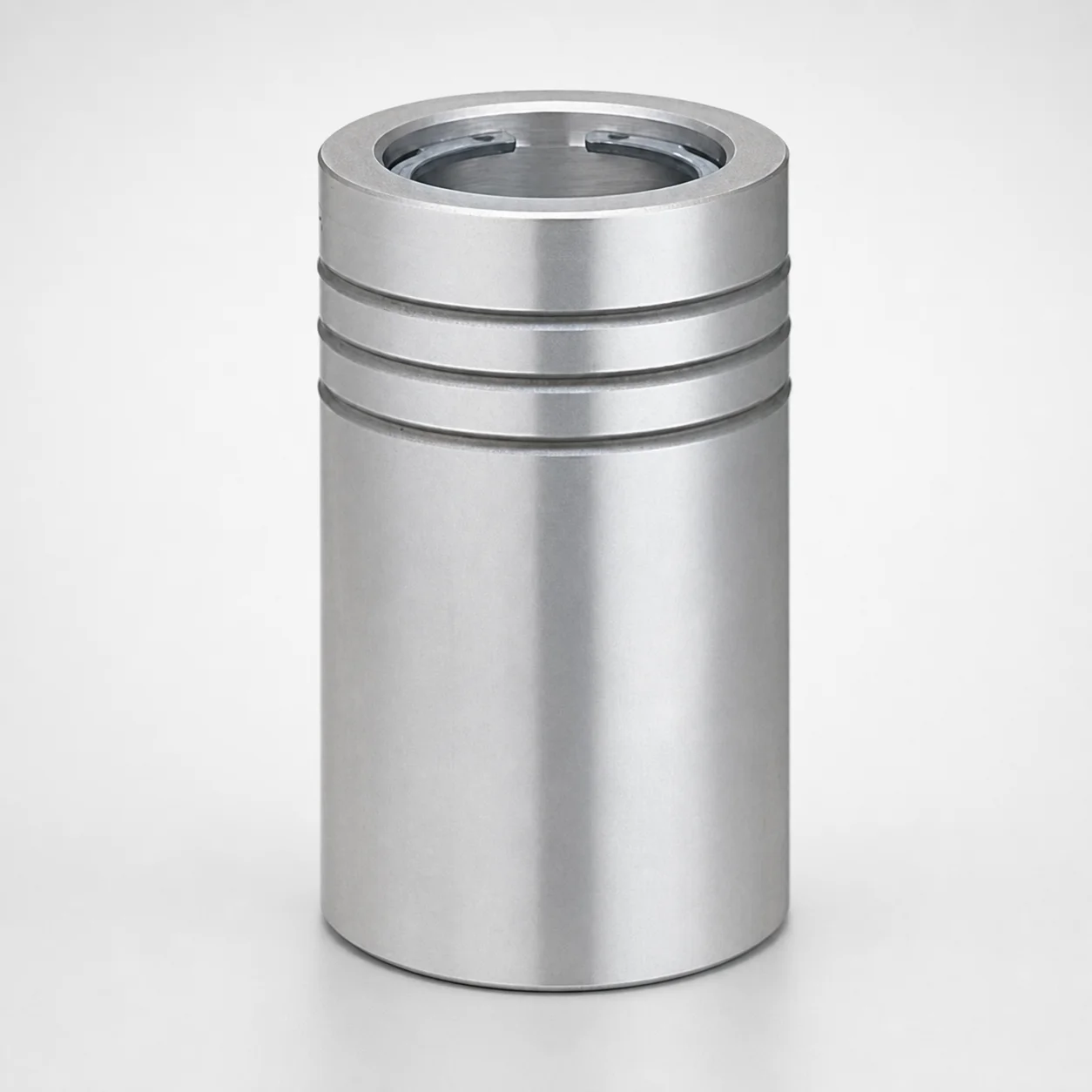
Ball Guide Bushings (LBBS) Loctite Bonded
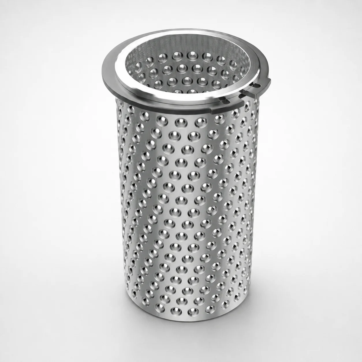
Aluminum Ball Cages for Guide Bushings with Groove & Circlip
Need Custom Specifications?
Our engineering team can help with custom configurations, material selection, and volume pricing.