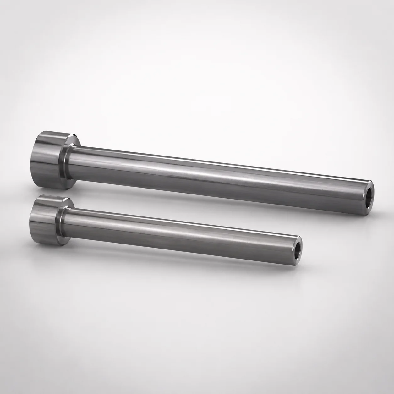
JIS Standard SKD61 Steel Nitrided Straight Ejector Sleeves
Straight ejector sleeves (SKD61 steel) with nitrided surface treatment support stable guidance in press molds. The single sleeve design and controlled concentricity help maintain consistent fit for efficient ejector action.
- Straight sleeve geometry with concentricity 0.06 for reliable hole/shaft alignment
- Durable SKD61 steel plus nitrided coating for improved wear resistance
- Inner diameter tolerance H7 to support proper clearance with ejector components
- JIS head type ESJ suited for standard mold ejector sleeve arrangements
Specifications
24 configurations available
| Head Thickness | Shaft Diameter Tolerance | D/P (Shaft Diameter) (mm) | V (Hole Diameter) (mm) | L (L dimension) (mm) | type |
|---|---|---|---|---|---|
| 6mm(JIS) | -0.01/-0.02 | 4 | 1.5 ~ 2.5 | 100 ~ 200 | - |
| 6mm(JIS) | -0.01/-0.02 | 4.5 | 1.5 ~ 2.5 | 100 ~ 200 | - |
| 6mm(JIS) | -0.01/-0.02 | 5 | 3 | 100 ~ 300 | - |
| 6mm(JIS) | -0.01/-0.02 | 5 | 2 ~ 3 | 100 ~ 300 | - |
| 6mm(JIS) | -0.01/-0.02 | 5.5 | 3 | 100 ~ 300 | - |
| 6mm(JIS) | -0.01/-0.02 | 5.5 | 2 ~ 3 | 100 ~ 300 | - |
| 6mm(JIS) | -0.01/-0.02 | 6 | 2 ~ 4 | 100 ~ 450 | - |
| 6mm(JIS) | -0.01/-0.02 | 6.5 | 2 ~ 4 | 100 ~ 450 | - |
| 6mm(JIS) | -0.01/-0.02 | 7 | 2 ~ 4.5 | 100 ~ 450 | - |
| 6mm(JIS) | -0.01/-0.02 | 7.5 | 3 ~ 4.5 | 100 ~ 375 | - |
| 8mm(JIS) | -0.01/-0.02 | 8 | 5 | 100 ~ 500 | - |
| 8mm(JIS) | -0.01/-0.02 | 8 | 2 ~ 5.5 | 100 ~ 500 | - |
| 8mm(JIS) | -0.01/-0.02 | 9 | 0.5 ~ 6 | 100 ~ 200 | - |
| 8mm(JIS) | -0.01/-0.02 | 9 | 2 ~ 5.5 | 100 ~ 200 | - |
| 8mm(JIS) | -0.01/-0.02 | 9 | 3 ~ 6 | 100 ~ 200 | - |
| 8mm(JIS) | -0.01/-0.02 | 9 | 0.5 ~ 6 | 225 ~ 500 | - |
| 8mm(JIS) | -0.01/-0.02 | 9 | 2 ~ 5.5 | 225 ~ 500 | - |
| 8mm(JIS) | -0.01/-0.02 | 9 | 3 ~ 6 | 225 ~ 500 | - |
| 8mm(JIS) | -0.01/-0.02 | 10 | 4 ~ 7 | 100 ~ 500 | - |
| 8mm(JIS) | -0.01/-0.02 | 12 | 8 | 100 ~ 500 | - |
| 8mm(JIS) | -0.01/-0.02 | 12 | 4 ~ 7 | 100 ~ 500 | - |
| 8mm(JIS) | -0.01/-0.02 | 12 | 8 ~ 8.5 | 100 ~ 500 | - |
| 8mm(JIS) | -0.01/-0.03 | 15 | 9 ~ 10 | 200 ~ 500 | - |
| 8mm(JIS) | -0.01/-0.03 | 20 | 12 ~ 15 | 200 ~ 500 | - |
Product Guide
Application Scenarios+
This nitrided ejector sleeve variant is used in straight ejector sleeve components for injection molds where repeatable alignment between the sleeve and ejector rod is critical. In automotive connector and housing molds, the controlled bore provides stable guidance as ejector pins/rods travel under high cycle loads, helping maintain smooth ejection and reducing risk of sticking.
It is also suited for appliance and consumer electronics housings that require consistent ejection stroke across multiple cavities. The nitrided surface and SKD61 steel base improve resistance to fretting and sliding wear, supporting long-term dimensional stability.
- Single-sleeve design simplifies assembly and standardizes fit in ejector arrangements.
- Concentricity 0.06 supports reliable alignment in the sleeve-to-shaft relationship.
- H7 inner diameter tolerance helps achieve the designed clearance for stable motion.
Material & Process Details+
JIS standard SKD61 steel (commonly associated with H13-class hot-work tool steels) is selected here to balance toughness for mold operation with adequate wear performance for ejector sliding interfaces. The sleeve is supplied with a nitrided surface treatment, which forms a hard, wear-resistant case that improves resistance to galling and surface fatigue.
Typical SKD61 nitrided ejector applications target a hardness in the mid-to-high HRC range after appropriate heat treatment, but the exact HRC value depends on the supplier’s process window and nitriding depth. The trade-off is that nitriding primarily increases surface hardness and wear resistance; the core toughness remains important to avoid cracking under intermittent shock loads.
- Before/after state: base material is SKD61, then nitrided for enhanced surface performance.
- Wear vs. toughness: harder surface with preserved core strength for reliable ejection.
Sizing & Selection Guide+
Select the sleeve using the specified shaft diameter (D/P) range and match the hole diameter (V) to the ejector or guiding geometry in your mold. For this product, D/P = 4 ~ 20 mm and V = 0.5 ~ 12 mm, so your ejector rod/shaft and the related locating feature should fall within these limits.
Then choose the required L (length) from 100 ~ 225 mm to cover the full guiding length needed for the stroke and expected side load. Confirm the sleeve-to-rod clearance by using the inner diameter tolerance H7 and the provided shaft diameter tolerance options (-0.01/-0.02 or -0.01/-0.03), which affect fit tightness.
- Use the head thickness as per JIS options: 6 mm or 8 mm.
- Maintain consistent concentricity (0.06) by selecting the correct bore/shaft pairing rather than forcing assembly.
Frequently Asked Questions
How do the H7 inner diameter tolerance and the provided shaft diameter tolerance range affect ejector clearance?+
This sleeve uses an inner diameter tolerance of H7, which sets the bore precision for stable guidance. When paired with ejector shafts sized within D/P = 4 ~ 20 mm, choose the matching shaft diameter tolerance option (-0.01/-0.02 or -0.01/-0.03) to achieve the intended running clearance. The tolerance combination directly influences risk of binding versus excessive play during ejection.
What does the stated concentricity 0.06 mean for alignment in straight ejector sleeve applications?+
The product specifies concentricity 0.06, which helps maintain consistent alignment between the sleeve bore and the locating axis. In molds with straight ejection paths, this improves shaft-to-bore tracking and supports smooth ejection. It also reduces sensitivity to minor assembly variations when the ejector arrangement is constrained by cavity layout.
Which length (L) should I select for a given ejector stroke and guiding requirement within the 100–225 mm range?+
Choose L = 100 ~ 225 mm so the guiding portion covers the full active travel and provides enough support against side loads. If the mold has longer ejection strokes or higher lateral load from part geometry, select toward the upper end of the range. Ensure the chosen length still clears surrounding mold components to avoid interference at max stroke.
What head thickness options (6 mm or 8 mm, JIS) are available and how do they influence compatibility with standard ejector sleeve arrangements?+
The head thickness is available in 6 mm (JIS) and 8 mm (JIS). The correct value should match the recess/seat depth in your standard ejector sleeve arrangement. Selecting the wrong head thickness can change the installed height, impacting alignment and clearance at the bore.
Why choose SKD61 with nitriding for ejector sleeves instead of relying on base steel alone?+
Using SKD61 as the base provides a tough tool-steel core suitable for mold operating conditions, while nitriding improves the sliding surface wear resistance. This combination is intended to reduce surface damage such as fretting and galling during repeated ejection cycles. For high-cycle molds where guidance stability matters, nitriding helps maintain performance over time by strengthening the surface where contact occurs.
Related Products
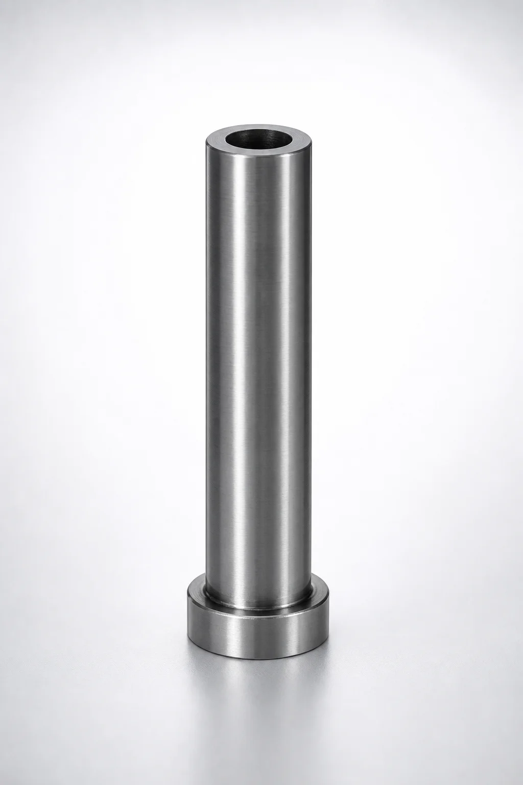
SKD61 Steel Short Straight Ejector Sleeves with Nitride Coating - Head T4
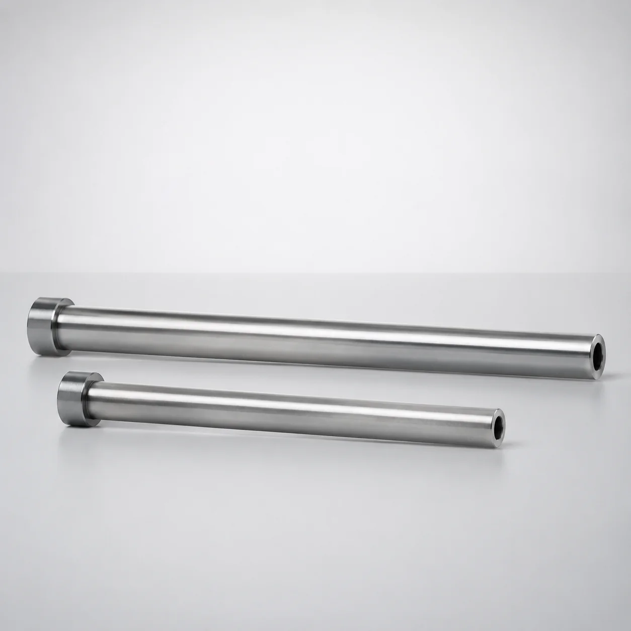
SKD61 Steel Nitrided Straight Ejector Sleeves (ESNV) Head T=4 mm
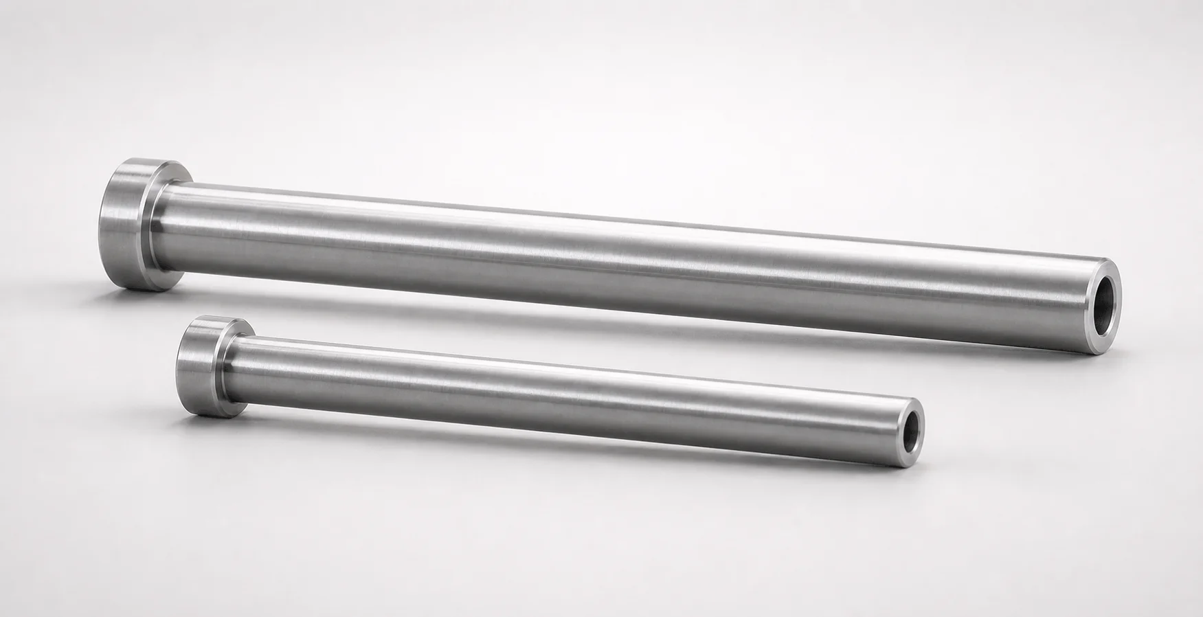
SKD61 Steel Nitrided Straight Ejector Sleeves
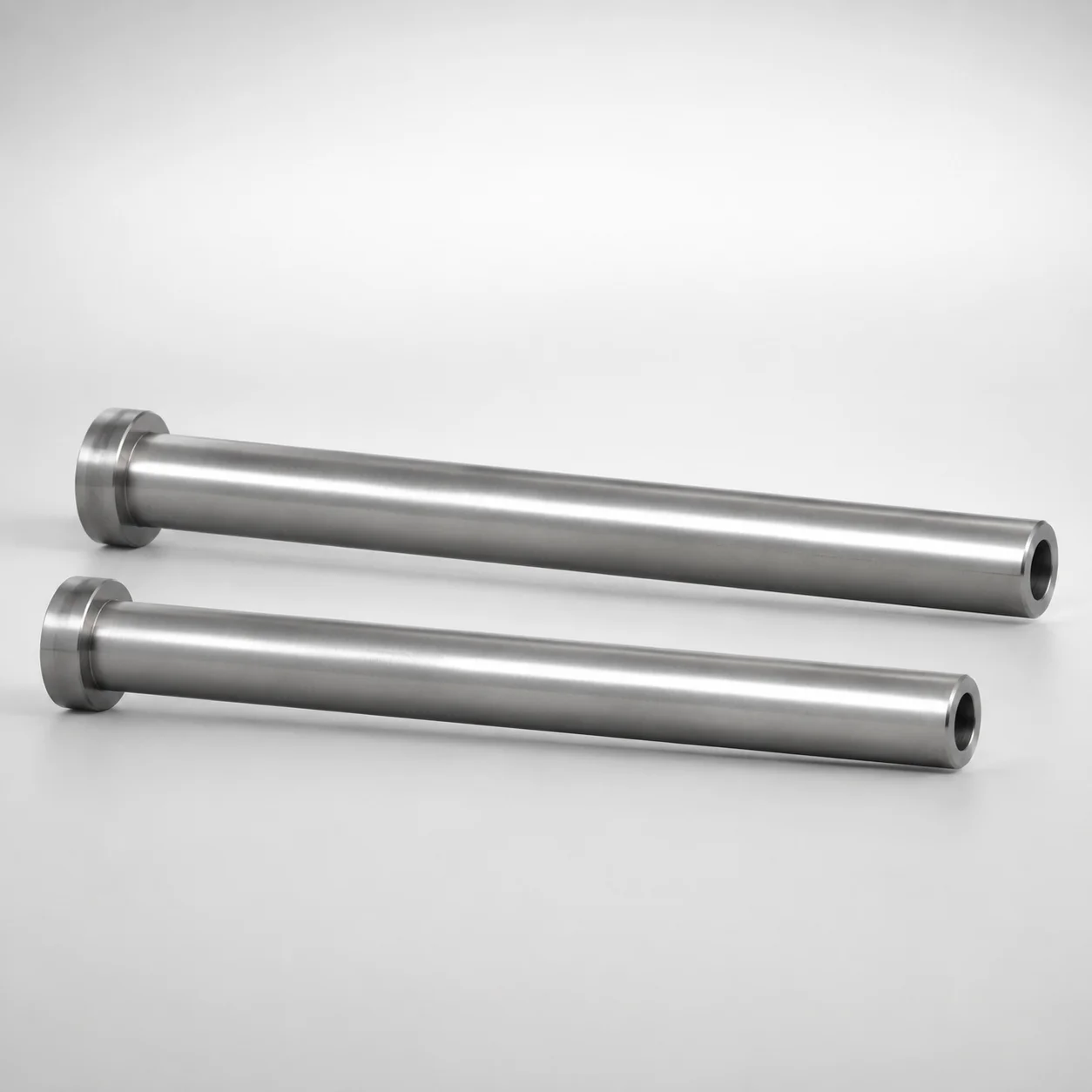
SKD61 Steel Nitrided Straight Ejector Sleeves Head T4
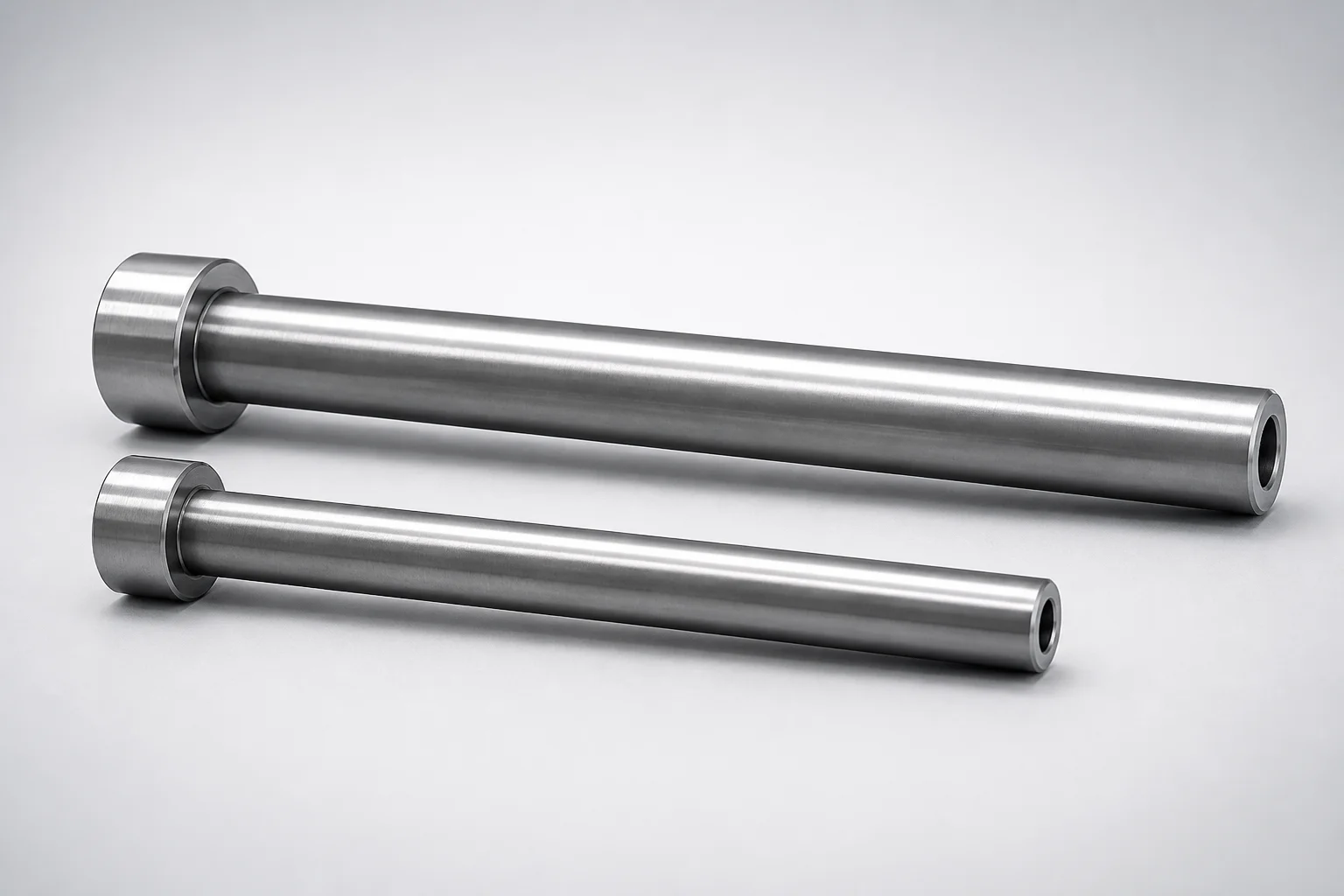
JIS Standard SKD61 Steel Nitrided Straight Ejector Sleeves H7 Bore
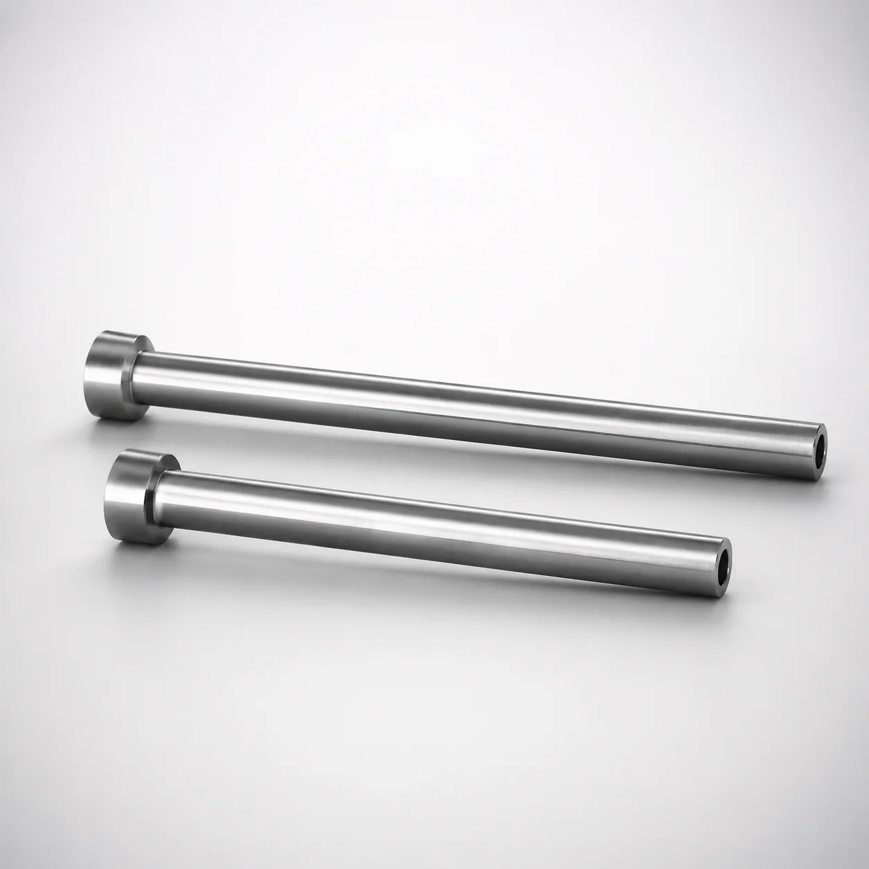
SKD61 Steel Nitrided Straight Ejector Sleeves
Need Custom Specifications?
Our engineering team can help with custom configurations, material selection, and volume pricing.