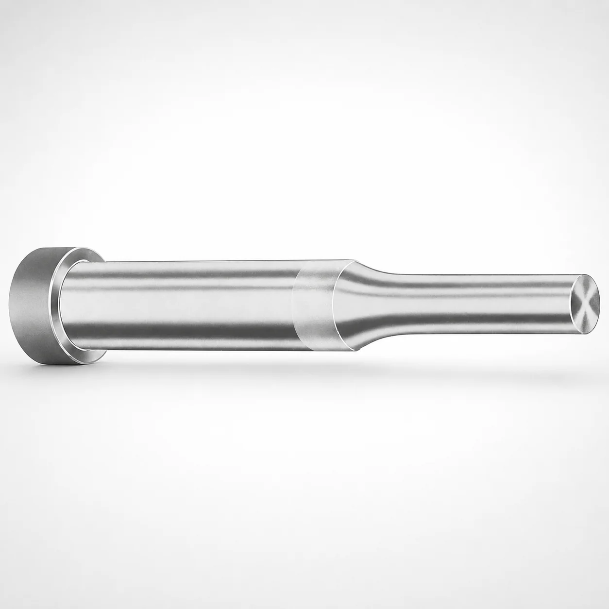
Regular Punches Metric XCDP Coating
Regular Punches Metric (DAYTON) with XCDP coating deliver consistent punching performance for metric die work. The standardized tooling format supports efficient procurement and dependable service life in production applications.
- Metric regular punch form supports consistent positioning in tooling assemblies
- XCDP coating helps improve wear resistance for repeated punch cycles
- Tip and point geometry options (X, R, K, O, H, L, J, N, V, Y, Z) match die requirements
- Made to support common metric punch applications where repeatable output matters
Specifications
318 configurations available
| Tip shape | Material | D (Shank dia.) (mm) | L1 (Point Length) (mm) | L (Length) (mm) | P Dimension (mm) | W Dimension (mm) | R Dimension (mm) |
|---|---|---|---|---|---|---|---|
| H | M2 | 04 | 8 ~ 13 | 40 ~ 100 | 1.3 ~ 3.95 | 1.3 ~ 1.59 | - |
| H | M2 | 04 | 8 ~ 13 | 40 ~ 100 | 1.3 ~ 3.95 | 1.6 ~ 3.95 | - |
| H | PS | 04 | 8 ~ 13 | 40 ~ 100 | 1.3 ~ 3.95 | 1.3 ~ 1.59 | - |
| H | PS | 04 | 8 ~ 13 | 40 ~ 100 | 1.3 ~ 3.95 | 1.6 ~ 3.95 | - |
| H | M2 | 05 | 13 ~ 19 | 40 ~ 100 | 1.6 ~ 4.95 | 1.6 ~ 4.95 | - |
| H | PS | 05 | 13 ~ 19 | 40 ~ 100 | 1.6 ~ 4.95 | 1.6 ~ 4.95 | - |
| H | M2 | 06 | 13 ~ 19 | 40 ~ 100 | 1.6 ~ 5.95 | 1.6 ~ 5.95 | - |
| H | PS | 06 | 13 ~ 19 | 40 ~ 100 | 1.6 ~ 5.95 | 1.6 ~ 5.95 | - |
| H | M2 | 08 | 19 ~ 25 | 50 ~ 100 | 2.5 ~ 7.95 | 2.5 ~ 7.95 | - |
| H | PS | 08 | 19 ~ 25 | 50 ~ 100 | 2.5 ~ 7.95 | 2.5 ~ 7.95 | - |
| H | M2 | 10 | 19 ~ 25 | 50 ~ 100 | 3.2 ~ 9.95 | 3.2 ~ 9.95 | - |
| H | PS | 10 | 19 ~ 25 | 50 ~ 100 | 3.2 ~ 9.95 | 3.2 ~ 9.95 | - |
| H | M2 | 13 | 19 ~ 25 | 50 ~ 100 | 4 ~ 12.95 | 4 ~ 4.49 | - |
| H | M2 | 13 | 19 ~ 25 | 50 ~ 100 | 4 ~ 12.95 | 4.5 ~ 12.95 | - |
| H | PS | 13 | 19 ~ 25 | 50 ~ 100 | 4 ~ 12.95 | 4 ~ 4.49 | - |
| H | PS | 13 | 19 ~ 25 | 50 ~ 100 | 4 ~ 12.95 | 4.5 ~ 12.95 | - |
| H | M2 | 16 | 19 ~ 25 | 50 ~ 100 | 6 ~ 15.95 | 6 ~ 15.95 | - |
| H | PS | 16 | 19 ~ 25 | 50 ~ 100 | 6 ~ 15.95 | 6 ~ 15.95 | - |
| H | M2 | 20 | 19 ~ 25 | 56 ~ 100 | 6 ~ 19.95 | 6 ~ 7.99 | - |
| H | M2 | 20 | 19 ~ 25 | 56 ~ 100 | 6 ~ 19.95 | 8 ~ 19.95 | - |
| H | PS | 20 | 19 ~ 25 | 56 ~ 100 | 6 ~ 19.95 | 6 ~ 7.99 | - |
| H | PS | 20 | 19 ~ 25 | 56 ~ 100 | 6 ~ 19.95 | 8 ~ 19.95 | - |
| H | M2 | 25 | 19 ~ 25 | 56 ~ 100 | 6 ~ 24.95 | 6 ~ 8.99 | - |
| H | M2 | 25 | 19 ~ 25 | 56 ~ 100 | 6 ~ 24.95 | 9 ~ 24.95 | - |
| H | PS | 25 | 19 ~ 25 | 56 ~ 100 | 6 ~ 24.95 | 6 ~ 8.99 | - |
| H | PS | 25 | 19 ~ 25 | 56 ~ 100 | 6 ~ 24.95 | 9 ~ 24.95 | - |
| H | M2 | 32 | 25 ~ 30 | 63 ~ 100 | 7.2 ~ 31.95 | 7.2 ~ 9.99 | - |
| H | M2 | 32 | 25 ~ 30 | 63 ~ 100 | 7.2 ~ 31.95 | 10 ~ 31.95 | - |
| H | PS | 32 | 25 ~ 30 | 63 ~ 100 | 7.2 ~ 31.95 | 7.2 ~ 9.99 | - |
| H | PS | 32 | 25 ~ 30 | 63 ~ 100 | 7.2 ~ 31.95 | 10 ~ 31.95 | - |
| J | M2 | 04 | 8 ~ 13 | 40 ~ 100 | 1.3 ~ 3.95 | 1.3 ~ 1.59 | - |
| J | M2 | 04 | 8 ~ 13 | 40 ~ 100 | 1.3 ~ 3.95 | 1.6 ~ 3.95 | - |
| J | PS | 04 | 8 ~ 13 | 40 ~ 100 | 1.3 ~ 3.95 | 1.3 ~ 1.59 | - |
| J | PS | 04 | 8 ~ 13 | 40 ~ 100 | 1.3 ~ 3.95 | 1.6 ~ 3.95 | - |
| J | M2 | 05 | 13 ~ 19 | 40 ~ 100 | 1.6 ~ 4.95 | 1.6 ~ 4.95 | - |
| J | PS | 05 | 13 ~ 19 | 40 ~ 100 | 1.6 ~ 4.95 | 1.6 ~ 4.95 | - |
| J | M2 | 06 | 13 ~ 19 | 40 ~ 100 | 1.6 ~ 5.95 | 1.6 ~ 5.95 | - |
| J | PS | 06 | 13 ~ 19 | 40 ~ 100 | 1.6 ~ 5.95 | 1.6 ~ 5.95 | - |
| J | M2 | 08 | 19 ~ 25 | 50 ~ 100 | 2.5 ~ 7.95 | 2.5 ~ 7.95 | - |
| J | PS | 08 | 19 ~ 25 | 50 ~ 100 | 2.5 ~ 7.95 | 2.5 ~ 7.95 | - |
| J | M2 | 10 | 19 ~ 25 | 50 ~ 100 | 3.2 ~ 9.95 | 3.2 ~ 9.95 | - |
| J | PS | 10 | 19 ~ 25 | 50 ~ 100 | 3.2 ~ 9.95 | 3.2 ~ 9.95 | - |
| J | M2 | 13 | 19 ~ 25 | 50 ~ 100 | 4 ~ 12.95 | 4 ~ 4.49 | - |
| J | M2 | 13 | 19 ~ 25 | 50 ~ 100 | 4 ~ 12.95 | 4.5 ~ 12.95 | - |
| J | PS | 13 | 19 ~ 25 | 50 ~ 100 | 4 ~ 12.95 | 4 ~ 4.49 | - |
| J | PS | 13 | 19 ~ 25 | 50 ~ 100 | 4 ~ 12.95 | 4.5 ~ 12.95 | - |
| J | M2 | 16 | 19 ~ 25 | 50 ~ 100 | 6 ~ 15.95 | 6 ~ 15.95 | - |
| J | PS | 16 | 19 ~ 25 | 50 ~ 100 | 6 ~ 15.95 | 6 ~ 15.95 | - |
| J | M2 | 20 | 19 ~ 25 | 56 ~ 100 | 6 ~ 19.95 | 6 ~ 7.99 | - |
| J | M2 | 20 | 19 ~ 25 | 56 ~ 100 | 6 ~ 19.95 | 8 ~ 19.95 | - |
Product Guide
Application Scenarios+
These metric regular punches are used in precision die sets where reliable alignment and consistent forming force matter across high-volume production. The XCDP coating variant is particularly suited for long-run punching of strip or sheet profiles, helping resist abrasive wear and reducing tip degradation after repeated cycles.
- Automotive and appliance stamped parts: Use the fixed-point regular punch geometry with metric shank diameters in the 4–32 mm range to match common die shoe and guide layouts, maintaining stable punching position during continuous operation.
- General industrial stamping: Select appropriate tip shapes (H, J, K, L, N, O, R, V, X, Y, Z) to suit the die cavity opening and part edge profile, while XCDP supports improved wear behavior under frequent punch repeats.
- Tooling programs requiring standardized procurement: The regular punch format supports easier maintenance and replacement planning in metric die work where the same punch family is reused across multiple production lots.
Material & Process Details+
This punch series is offered in two steels: M2 and PS. M2 (tool steel, commonly aligned with the AISI M2 family) is selected when higher wear resistance and improved cutting edge stability are priorities for punching applications. PS is typically chosen where toughness and manufacturing convenience are balanced for routine production punching.
- XCDP coating: Adds surface protection to reduce wear during repeated punch cycles.
- Heat treatment (typical for punches): Both steel options are generally provided in a hardened, tempered state to achieve usable hardness while maintaining edge toughness for stable cutting.
- Hardness/toughness trade-off: M2 generally supports higher wear performance; PS may offer a more forgiving toughness profile depending on the supplied temper.
Exact hardness in HRC is not specified in the provided data, so hardness should be confirmed per batch or C of C documentation.
Sizing & Selection Guide+
To select the correct punch size, start with the shank diameter D (4–32 mm) so the punch fits the corresponding die holder/punch guide bushing and maintains concentric alignment. Next, match the overall punch length L (40–100, 50–100, 56–100, 63–100 mm) to your die set height and stripper/guide stack-up, ensuring sufficient protrusion for the point while avoiding interference.
- Point length L1 (8–13, 13–19, 19–25, 25–30 mm): Choose based on penetration depth required to form the cavity opening cleanly.
- P and W dimensions (P: 0.8–10 mm; W: 1.3–10 mm): Use these to align with the specific tip geometry engagement features for the chosen tip shape.
- Tip shape: Select from H, J, K, L, N, O, R, V, X, Y, Z to match the die opening edge profile and desired burr/finish behavior.
- Tolerance/fit: Verify fit clearance in the punch guide for the selected D; tight fits can improve positional repeatability but may increase binding if stack tolerances accumulate.
These dimensions are provided as spec ranges; confirm the exact part drawing for your required combination of D, L, L1, P, W.
Frequently Asked Questions
Which shank diameter (D) range should I select for metric punch tooling compatibility?+
Select the punch D (shank dia.) in the 4–32 mm range to match your punch guide bushing and die holder bore. Using the correct D is key for maintaining concentricity and stable alignment during punching. Confirm the guide bore tolerance and any fit clearance requirements for your die set stack-up.
How do I choose the correct point length (L1) and overall length (L) for the required penetration depth?+
Choose L1 from 8–13, 13–19, 19–25, or 25–30 mm based on the penetration depth needed to form the cavity opening. Then select L from the available ranges (40–100, 50–100, 56–100, 63–100 mm) so the punch protrusion works with your stripper/guide height. This prevents under-penetration and avoids interference with die components.
What tip shapes are available, and how do they relate to the die opening geometry?+
This series lists multiple tip shape options: H, J, K, L, N, O, R, V, X, Y, Z. Use the tip shape that corresponds to your die cavity edge profile and the part edge finish requirements. The related P (0.8–10 mm) and W (1.3–10 mm) dimensions should also be matched to the chosen tip geometry.
When should I choose M2 vs PS steel for regular punches with XCDP coating?+
The punch series is offered in M2 and PS materials. Choose M2 when higher wear resistance and edge stability under repeated punching are the main drivers. Choose PS when you need a balanced toughness profile for routine production. Final selection should be validated with your cutting speed, material hardness, and cycle count.
What benefits does the XCDP coating provide for production punching?+
The variant with XCDP coating is designed to improve wear resistance during repeated punch cycles. In practical die work, this helps slow down tip wear and supports more consistent punching performance over longer intervals. For critical applications, confirm coating durability requirements against your target material and cycle rate.
Related Products






Need Custom Specifications?
Our engineering team can help with custom configurations, material selection, and volume pricing.