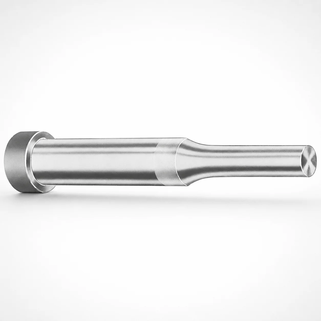
Inch Regular Punches XNAP Coating
Inch regular punches (XNAP coating) are designed for reliable punching performance in tool and die operations, delivering stable wear protection and predictable part-to-part identification. DAYTON Lamina standardized the part number format to simplify ordering and specification control across DAYTON and Lamina brands.
- XNAP coating for improved wear resistance during repeated punching cycles
- Multiple tip shape options (X, R, K, O, H, L, J, N, V, Y, Z) for process fit
- Coordinated point length coding supports consistent setup and downstream tool compatibility
- Uses DAYTON Lamina standardized part number format to reduce selection errors
Specifications
882 configurations available
| Tip shape | D (Shank dia.) (in) | Standard [S] Point Length B & L (Length) (coded inch) | Alternate [B] Point Length B & L (Length) (coded inch) | Alternate [C] Point Length B & L (Length) (coded inch) | Alternate [D] Point Length B & L (Length) (coded inch) | Alternate [E] Point Length B & L (Length) (coded inch) | P Dimension (in) | W Dimension (in) | R Dimension (in) |
|---|---|---|---|---|---|---|---|---|---|
| H | 12(0.1250") | - | 150 ~ 400 | - | - | - | 0.062 ~ 0.125 | 0.062 ~ 0.125 | - |
| H | 12(0.1250") | 150 ~ 400 | - | - | - | - | 0.062 ~ 0.125 | 0.062 ~ 0.125 | - |
| H | 18(0.1875") | - | 150 ~ 500 | - | - | - | 0.062 ~ 0.1875 | 0.062 ~ 0.1875 | - |
| H | 18(0.1875") | 150 ~ 500 | - | - | - | - | 0.062 ~ 0.1875 | 0.062 ~ 0.1875 | - |
| H | 25(0.2500") | - | 150 ~ 600 | - | - | - | 0.062 ~ 0.25 | 0.062 ~ 0.0929 | - |
| H | 25(0.2500") | - | 150 ~ 600 | - | - | - | 0.062 ~ 0.25 | 0.093 ~ 0.25 | - |
| H | 25(0.2500") | 150 ~ 600 | - | - | - | - | 0.062 ~ 0.25 | 0.062 ~ 0.0929 | - |
| H | 25(0.2500") | 150 ~ 600 | - | - | - | - | 0.062 ~ 0.25 | 0.093 ~ 0.25 | - |
| H | 31(0.3125") | - | 150 ~ 600 | - | - | - | 0.062 ~ 0.3125 | 0.062 ~ 0.1249 | - |
| H | 31(0.3125") | - | 150 ~ 600 | - | - | - | 0.062 ~ 0.3125 | 0.125 ~ 0.3125 | - |
| H | 31(0.3125") | - | - | 175 ~ 600 | - | - | 0.062 ~ 0.3125 | 0.062 ~ 0.1249 | - |
| H | 31(0.3125") | - | - | 175 ~ 600 | - | - | 0.062 ~ 0.3125 | 0.125 ~ 0.3125 | - |
| H | 31(0.3125") | 150 ~ 600 | - | - | - | - | 0.062 ~ 0.3125 | 0.062 ~ 0.1249 | - |
| H | 31(0.3125") | 150 ~ 600 | - | - | - | - | 0.062 ~ 0.3125 | 0.125 ~ 0.3125 | - |
| H | 37(0.3750") | - | 175 ~ 600 | - | - | - | 0.08 ~ 0.375 | 0.08 ~ 0.1869 | - |
| H | 37(0.3750") | - | 175 ~ 600 | - | - | - | 0.08 ~ 0.375 | 0.187 ~ 0.375 | - |
| H | 37(0.3750") | - | - | 175 ~ 600 | - | - | 0.08 ~ 0.375 | 0.08 ~ 0.1869 | - |
| H | 37(0.3750") | - | - | 175 ~ 600 | - | - | 0.08 ~ 0.375 | 0.187 ~ 0.375 | - |
| H | 37(0.3750") | - | - | - | 200 ~ 600 | - | 0.08 ~ 0.375 | 0.08 ~ 0.1869 | - |
| H | 37(0.3750") | - | - | - | 200 ~ 600 | - | 0.08 ~ 0.375 | 0.187 ~ 0.375 | - |
| H | 37(0.3750") | 175 ~ 600 | - | - | - | - | 0.08 ~ 0.375 | 0.08 ~ 0.1869 | - |
| H | 37(0.3750") | 175 ~ 600 | - | - | - | - | 0.08 ~ 0.375 | 0.187 ~ 0.375 | - |
| H | 43(0.4375") | - | - | 200 ~ 700 | - | - | 0.158 ~ 0.4374 | 0.158 ~ 0.1869 | - |
| H | 43(0.4375") | - | - | 200 ~ 700 | - | - | 0.158 ~ 0.4374 | 0.187 ~ 0.4374 | - |
| H | 43(0.4375") | - | - | - | 200 ~ 700 | - | 0.158 ~ 0.4374 | 0.158 ~ 0.1869 | - |
| H | 43(0.4375") | - | - | - | 200 ~ 700 | - | 0.158 ~ 0.4374 | 0.187 ~ 0.4374 | - |
| H | 43(0.4375") | 200 ~ 700 | - | - | - | - | 0.158 ~ 0.4374 | 0.158 ~ 0.1869 | - |
| H | 43(0.4375") | 200 ~ 700 | - | - | - | - | 0.158 ~ 0.4374 | 0.187 ~ 0.4374 | - |
| H | 50(0.5000") | - | - | 200 ~ 700 | - | - | 0.158 ~ 0.5 | 0.158 ~ 0.1869 | - |
| H | 50(0.5000") | - | - | 200 ~ 700 | - | - | 0.158 ~ 0.5 | 0.187 ~ 0.5 | - |
| H | 50(0.5000") | - | - | - | 200 ~ 700 | - | 0.158 ~ 0.5 | 0.158 ~ 0.1869 | - |
| H | 50(0.5000") | - | - | - | 200 ~ 700 | - | 0.158 ~ 0.5 | 0.187 ~ 0.5 | - |
| H | 50(0.5000") | 200 ~ 700 | - | - | - | - | 0.158 ~ 0.5 | 0.158 ~ 0.1869 | - |
| H | 50(0.5000") | 200 ~ 700 | - | - | - | - | 0.158 ~ 0.5 | 0.187 ~ 0.5 | - |
| H | 62(0.6250") | - | - | - | 225 ~ 700 | - | 0.235 ~ 0.625 | 0.25 ~ 0.625 | - |
| H | 62(0.6250") | - | - | - | 225 ~ 700 | - | 0.235 ~ 0.625 | 0.235 ~ 0.2499 | - |
| H | 62(0.6250") | - | - | - | - | 225 ~ 700 | 0.235 ~ 0.625 | 0.25 ~ 0.625 | - |
| H | 62(0.6250") | - | - | - | - | 225 ~ 700 | 0.235 ~ 0.625 | 0.235 ~ 0.2499 | - |
| H | 62(0.6250") | 225 ~ 700 | - | - | - | - | 0.235 ~ 0.625 | 0.25 ~ 0.625 | - |
| H | 62(0.6250") | 225 ~ 700 | - | - | - | - | 0.235 ~ 0.625 | 0.235 ~ 0.2499 | - |
| H | 75(0.7500") | - | - | - | 225 ~ 700 | - | 0.235 ~ 0.75 | 0.235 ~ 0.3119 | - |
| H | 75(0.7500") | - | - | - | 225 ~ 700 | - | 0.235 ~ 0.75 | 0.312 ~ 0.75 | - |
| H | 75(0.7500") | - | - | - | - | 225 ~ 700 | 0.235 ~ 0.75 | 0.235 ~ 0.3119 | - |
| H | 75(0.7500") | - | - | - | - | 225 ~ 700 | 0.235 ~ 0.75 | 0.312 ~ 0.75 | - |
| H | 75(0.7500") | 225 ~ 700 | - | - | - | - | 0.235 ~ 0.75 | 0.235 ~ 0.3119 | - |
| H | 75(0.7500") | 225 ~ 700 | - | - | - | - | 0.235 ~ 0.75 | 0.312 ~ 0.75 | - |
| H | 87(0.8750") | - | - | - | 225 ~ 700 | - | 0.235 ~ 0.875 | 0.235 ~ 0.3119 | - |
| H | 87(0.8750") | - | - | - | 225 ~ 700 | - | 0.235 ~ 0.875 | 0.312 ~ 0.875 | - |
| H | 87(0.8750") | - | - | - | - | 225 ~ 700 | 0.235 ~ 0.875 | 0.235 ~ 0.3119 | - |
| H | 87(0.8750") | - | - | - | - | 225 ~ 700 | 0.235 ~ 0.875 | 0.312 ~ 0.875 | - |
Product Guide
Application Scenarios+
In injection mold tooling, inch regular punches with an XNAP coating are typically used in tool/die station inserts and secondary forming steps where repeatable piercing and material shearing are required. They are well suited for automotive connector and terminal tooling, helping maintain consistent cutting edge behavior across large production runs while supporting reliable part-to-part identification.
- Automotive connector molds: Use the standardized point length coding to match downstream knock-out, stripper, or forming alignment requirements.
- Packaging and electrical housings: The XNAP-coated punch face supports stable wear protection during repeated punching cycles in high-cycle operations.
- General production tool assemblies: Select the tip shape option (X, R, K, O, H, L, J, N, V, Y, Z) to optimize contact geometry for the specific workpiece and process conditions.
The DAYTON Lamina standardized part numbering structure reduces specification drift between tool builds, simplifying setup verification and interchangeability across stations.
Material & Process Details+
The provided series information specifies the XNAP coating and dimensional/tip code options, but it does not list a specific steel grade or hardness value. Therefore, this page should treat the steel and heat treatment as application-dependent per the supplier’s punch material selection.
From a materials perspective, the key performance attribute here is the XNAP coating, chosen to enhance wear resistance during repeated punching cycles. In practice, improved surface durability helps stabilize edge condition, which supports consistent forming/punching force and reduces variance over time.
- Coating-first differentiation: Focus selection on XNAP for wear protection when cycling is the dominant failure mode.
- Steel/heat treatment: Confirm the exact base material, quench/temper or other heat treatment state, and target hardness (HRC) for your die block and workpiece combination.
If multiple base steels are offered for this series, compare them by toughness vs. wear trade-offs after heat treatment, using your expected shock loading and cutting speed as the primary inputs.
Sizing & Selection Guide+
Correct punch sizing starts with matching shank diameter (D) and point length codes to the receiving plate/tooling geometry. For this inch regular punch series, D is specified in the range 12 ~ 250 (in), and point length codes cover 150 ~ 250 for the standard [S] option. Alternate point length ranges expand up to 150 ~ 400, 150 ~ 500, 150 ~ 600, 175 ~ 600, 200 ~ 700, 225 ~ 700, and 250 ~ 700, depending on the [B]/[C]/[D]/[E] coding family.
- Match cavity/core interface: Use the coded point length to ensure the punch protrusion and working length align with the cavity/core or sub-plate opening depth.
- Tolerance/fit: Ensure D and any guided features in your punch holder maintain the intended clearance/press fit; verify dimensional and alignment requirements with your tool supplier drawings.
- Geometry selection: Choose the tip shape (H, J, K, L, N, O, R, V, X, Y, Z) to control penetration profile without changing base dimensions.
Track the coding-based dimensions (standard vs alternate point length options) as they are effectively configurable for different tool heights and contact depths.
Frequently Asked Questions
Which dimensions in the XNAP inch regular punch series control the working penetration in my tool?+
The primary working length control is the point length code, provided as standard [S] 150 ~ 250 and alternate ranges depending on the coding family: [B] up to 150 ~ 600 (various sets), [C] up to 200 ~ 700, and additional alternate options [D]/[E] that reach 225 ~ 700 and 250 ~ 700.
The second key dimension is D (shank dia.) 12 ~ 250, which must match your holder and guidance features.
How do I select the correct tip shape (X, R, K, O, H, L, J, N, V, Y, Z) for consistent punch forming?+
Tip shapes in this series are selectable across H, J, K, L, N, O, R, V, X, Y, Z to tune contact geometry for your punching/forming behavior. Use the tip shape that best matches the intended shearing/penetration profile of the workpiece.
After choosing tip geometry, verify that the point length coding matches your tool’s required protrusion so the edge contacts the workpiece at the intended depth.
What does the XNAP coating choice change versus selecting different point length options?+
In this series, XNAP coating is the performance differentiator aimed at improved wear resistance during repeated punching cycles.
Point length options control how far the punch works (standard 150 ~ 250 and alternates up to 700 depending on code family). Coating choice affects edge wear behavior, while point length affects tool setup and penetration depth.
When does the shank diameter D (12 ~ 250) become the limiting dimension for compatibility?+
D (Shank dia.) is specified as 12 ~ 250 (in) and becomes the limiting factor when your punch holder, guide bushing, or locating bore defines the allowable shank size.
Before ordering, confirm your holder guidance and any fit requirements against the intended D value, then select the point length code to achieve the correct protrusion.
Are the point length dimensions fixed, or are they code-configurable for different tool heights?+
Point length is code-configurable in this series. The standard option is [S] 150 ~ 250, while alternate coding families provide extended ranges such as [B] 150 ~ 400 / 150 ~ 500 / 150 ~ 600, [C] 175 ~ 600 / 200 ~ 700, and [D]/[E] options reaching 225 ~ 700 and 250 ~ 700.
This allows you to adapt punch working length to different die heights without changing tip shape selection.
Related Products






Need Custom Specifications?
Our engineering team can help with custom configurations, material selection, and volume pricing.