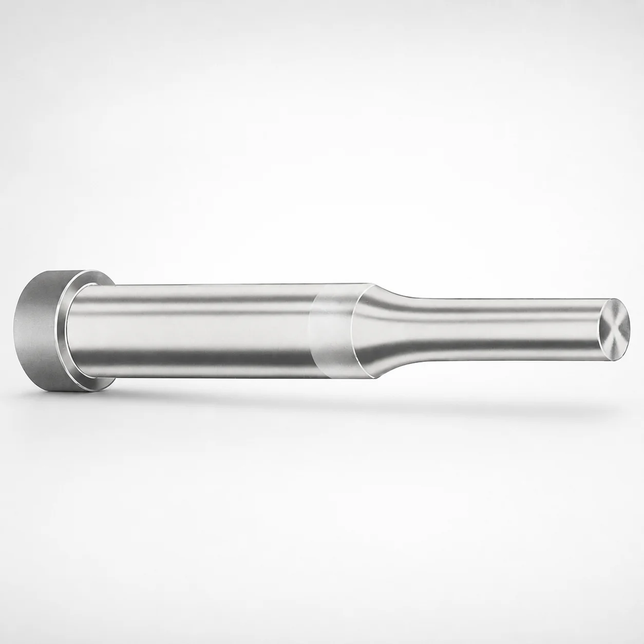
Regular Punches Inch XCD Coating
Regular Punches Inch XCD Coating are designed for reliable punching operations where consistent fit and tool life matter. Built on the Dayton Lamina part number standard, they simplify identification, procurement, and maintenance planning.
- Inch-series regular punch geometry for stable punching performance
- XCD coating option to support wear resistance in production
- Standardized part number format improves cross-referencing and ordering accuracy
- Suitable for die sets and industrial stamping tool applications
Specifications
882 configurations available
| Tip shape | D (Shank dia.) (in) | Standard [S] Point Length B & L (Length) (coded inch) | Alternate [B] Point Length B & L (Length) (coded inch) | Alternate [C] Point Length B & L (Length) (coded inch) | Alternate [D] Point Length B & L (Length) (coded inch) | Alternate [E] Point Length B & L (Length) (coded inch) | P Dimension (in) | W Dimension (in) | R Dimension (in) |
|---|---|---|---|---|---|---|---|---|---|
| H | 12(0.1250") | - | 150 ~ 400 | - | - | - | 0.062 ~ 0.125 | 0.062 ~ 0.125 | - |
| H | 12(0.1250") | 150 ~ 400 | - | - | - | - | 0.062 ~ 0.125 | 0.062 ~ 0.125 | - |
| H | 18(0.1875") | - | 150 ~ 500 | - | - | - | 0.062 ~ 0.1875 | 0.062 ~ 0.1875 | - |
| H | 18(0.1875") | 150 ~ 500 | - | - | - | - | 0.062 ~ 0.1875 | 0.062 ~ 0.1875 | - |
| H | 25(0.2500") | - | 150 ~ 600 | - | - | - | 0.062 ~ 0.25 | 0.062 ~ 0.0929 | - |
| H | 25(0.2500") | - | 150 ~ 600 | - | - | - | 0.062 ~ 0.25 | 0.093 ~ 0.25 | - |
| H | 25(0.2500") | 150 ~ 600 | - | - | - | - | 0.062 ~ 0.25 | 0.062 ~ 0.0929 | - |
| H | 25(0.2500") | 150 ~ 600 | - | - | - | - | 0.062 ~ 0.25 | 0.093 ~ 0.25 | - |
| H | 31(0.3125") | - | 150 ~ 600 | - | - | - | 0.062 ~ 0.3125 | 0.062 ~ 0.1249 | - |
| H | 31(0.3125") | - | 150 ~ 600 | - | - | - | 0.062 ~ 0.3125 | 0.125 ~ 0.3125 | - |
| H | 31(0.3125") | - | - | 175 ~ 600 | - | - | 0.062 ~ 0.3125 | 0.062 ~ 0.1249 | - |
| H | 31(0.3125") | - | - | 175 ~ 600 | - | - | 0.062 ~ 0.3125 | 0.125 ~ 0.3125 | - |
| H | 31(0.3125") | 150 ~ 600 | - | - | - | - | 0.062 ~ 0.3125 | 0.062 ~ 0.1249 | - |
| H | 31(0.3125") | 150 ~ 600 | - | - | - | - | 0.062 ~ 0.3125 | 0.125 ~ 0.3125 | - |
| H | 37(0.3750") | - | 175 ~ 600 | - | - | - | 0.08 ~ 0.375 | 0.08 ~ 0.1869 | - |
| H | 37(0.3750") | - | 175 ~ 600 | - | - | - | 0.08 ~ 0.375 | 0.187 ~ 0.375 | - |
| H | 37(0.3750") | - | - | 175 ~ 600 | - | - | 0.08 ~ 0.375 | 0.08 ~ 0.1869 | - |
| H | 37(0.3750") | - | - | 175 ~ 600 | - | - | 0.08 ~ 0.375 | 0.187 ~ 0.375 | - |
| H | 37(0.3750") | - | - | - | 200 ~ 600 | - | 0.08 ~ 0.375 | 0.08 ~ 0.1869 | - |
| H | 37(0.3750") | - | - | - | 200 ~ 600 | - | 0.08 ~ 0.375 | 0.187 ~ 0.375 | - |
| H | 37(0.3750") | 175 ~ 600 | - | - | - | - | 0.08 ~ 0.375 | 0.08 ~ 0.1869 | - |
| H | 37(0.3750") | 175 ~ 600 | - | - | - | - | 0.08 ~ 0.375 | 0.187 ~ 0.375 | - |
| H | 43(0.4375") | - | - | 200 ~ 700 | - | - | 0.158 ~ 0.4374 | 0.158 ~ 0.1869 | - |
| H | 43(0.4375") | - | - | 200 ~ 700 | - | - | 0.158 ~ 0.4374 | 0.187 ~ 0.4374 | - |
| H | 43(0.4375") | - | - | - | 200 ~ 700 | - | 0.158 ~ 0.4374 | 0.158 ~ 0.1869 | - |
| H | 43(0.4375") | - | - | - | 200 ~ 700 | - | 0.158 ~ 0.4374 | 0.187 ~ 0.4374 | - |
| H | 43(0.4375") | 200 ~ 700 | - | - | - | - | 0.158 ~ 0.4374 | 0.158 ~ 0.1869 | - |
| H | 43(0.4375") | 200 ~ 700 | - | - | - | - | 0.158 ~ 0.4374 | 0.187 ~ 0.4374 | - |
| H | 50(0.5000") | - | - | 200 ~ 700 | - | - | 0.158 ~ 0.5 | 0.158 ~ 0.1869 | - |
| H | 50(0.5000") | - | - | 200 ~ 700 | - | - | 0.158 ~ 0.5 | 0.187 ~ 0.5 | - |
| H | 50(0.5000") | - | - | - | 200 ~ 700 | - | 0.158 ~ 0.5 | 0.158 ~ 0.1869 | - |
| H | 50(0.5000") | - | - | - | 200 ~ 700 | - | 0.158 ~ 0.5 | 0.187 ~ 0.5 | - |
| H | 50(0.5000") | 200 ~ 700 | - | - | - | - | 0.158 ~ 0.5 | 0.158 ~ 0.1869 | - |
| H | 50(0.5000") | 200 ~ 700 | - | - | - | - | 0.158 ~ 0.5 | 0.187 ~ 0.5 | - |
| H | 62(0.6250") | - | - | - | 225 ~ 700 | - | 0.235 ~ 0.625 | 0.25 ~ 0.625 | - |
| H | 62(0.6250") | - | - | - | 225 ~ 700 | - | 0.235 ~ 0.625 | 0.235 ~ 0.2499 | - |
| H | 62(0.6250") | - | - | - | - | 225 ~ 700 | 0.235 ~ 0.625 | 0.25 ~ 0.625 | - |
| H | 62(0.6250") | - | - | - | - | 225 ~ 700 | 0.235 ~ 0.625 | 0.235 ~ 0.2499 | - |
| H | 62(0.6250") | 225 ~ 700 | - | - | - | - | 0.235 ~ 0.625 | 0.25 ~ 0.625 | - |
| H | 62(0.6250") | 225 ~ 700 | - | - | - | - | 0.235 ~ 0.625 | 0.235 ~ 0.2499 | - |
| H | 75(0.7500") | - | - | - | 225 ~ 700 | - | 0.235 ~ 0.75 | 0.235 ~ 0.3119 | - |
| H | 75(0.7500") | - | - | - | 225 ~ 700 | - | 0.235 ~ 0.75 | 0.312 ~ 0.75 | - |
| H | 75(0.7500") | - | - | - | - | 225 ~ 700 | 0.235 ~ 0.75 | 0.235 ~ 0.3119 | - |
| H | 75(0.7500") | - | - | - | - | 225 ~ 700 | 0.235 ~ 0.75 | 0.312 ~ 0.75 | - |
| H | 75(0.7500") | 225 ~ 700 | - | - | - | - | 0.235 ~ 0.75 | 0.235 ~ 0.3119 | - |
| H | 75(0.7500") | 225 ~ 700 | - | - | - | - | 0.235 ~ 0.75 | 0.312 ~ 0.75 | - |
| H | 87(0.8750") | - | - | - | 225 ~ 700 | - | 0.235 ~ 0.875 | 0.235 ~ 0.3119 | - |
| H | 87(0.8750") | - | - | - | 225 ~ 700 | - | 0.235 ~ 0.875 | 0.312 ~ 0.875 | - |
| H | 87(0.8750") | - | - | - | - | 225 ~ 700 | 0.235 ~ 0.875 | 0.235 ~ 0.3119 | - |
| H | 87(0.8750") | - | - | - | - | 225 ~ 700 | 0.235 ~ 0.875 | 0.312 ~ 0.875 | - |
Product Guide
Application Scenarios+
These inch-series regular punches are used in production die sets and industrial stamping operations where tooling repeatability and predictable wear behavior are required. The punch geometry is selected from tip shapes H, J, K, L, N, O, R, V, X, Y, Z, enabling engineers to match cutting profiles for different strip thicknesses and part edge requirements.
- Automotive and appliance stamping: choose compatible shank diameter D (12–250 in) and coded point length ranges to maintain consistent alignment through the die block, supporting stable punching cycles with the XCD coating to improve surface durability.
- Electrical connector and sheet-metal brackets: select the appropriate P (0.042–1.625 in) and W (0.062–0.5 in) dimensions to control punch land/contact area and reduce rapid rounding during high-volume runs.
- General fabrication multi-cavity tooling: standardized part number structure simplifies internal matching for maintenance planning and reduces downtime caused by misidentification.
Material & Process Details+
The provided datasheet specifies the XCD coating option as the primary performance layer for these regular punches. XCD coating is selected to improve wear resistance at the punch working edge, helping retain dimensional stability over repeated strokes in stamping environments.
- Wear vs. toughness trade-off: coated punch tips typically prioritize surface hardness and abrasion resistance; however, edge impact toughness is still governed by the underlying punch steel grade and heat treatment (not specified in the input data).
- Manufacturing process (general): the punch blank is precision-ground to inch-series geometry, followed by coating application to the working surfaces to resist scoring and micro-wear.
- Heat treatment: the input does not list a specific steel grade or hardness (HRC) or a defined heat-treatment state (e.g., quenched & tempered, nitrided), so these values should be confirmed with your Dayton/DAYTON technical sheet before hard-matching to existing tools.
Sizing & Selection Guide+
Select dimensions by matching the punch shank and point geometry to your existing die layout and cutting requirements. First choose the correct tip shape (H, J, K, L, N, O, R, V, X, Y, Z) based on the required cutting edge profile for the part geometry.
- Shank diameter: set D (12–250 in) to match your holder and guiding components so the punch stays centered through the die set.
- Point length: use the coded Standard [S] point length B & L range 150–250 (coded inch), or select an Alternate [B] or Alternate [C]/[D]/[E] option using the provided coded ranges (e.g., Alternate [B] 150–400, 150–500, 150–600; Alternate [D] 200–600/200–700/225–700; Alternate [E] 250–700).
- Edge/contact control: size P (0.042–1.625 in) and W (0.062–0.5 in) to align with your target clearance and cutting pressure; R is fixed at 0.007 in per the parameter list.
Because exact tolerances are not provided, confirm fit classes with your toolmaker for the interface between the punch shank and die components.
Frequently Asked Questions
How do I choose the correct tip shape (H, J, K, L, N, O, R, V, X, Y, Z) for my stamping profile?+
Use the required cutting edge profile for the part geometry and strip material behavior. Match the intended punch working outline by selecting one of the listed tip shapes, then verify that your chosen shank diameter D (12–250 in) and coded point length range fit the die/tool stack-up.
The XCD coating is an option for improving wear during production, but it should be selected after geometry compatibility is confirmed.
Which coded point length ranges should I consider when replacing an existing regular punch?+
Start with the Standard [S] point length coded range 150–250, then check alternates if your tool stack-up differs. The input lists alternate coded ranges for [B] (150–400, 150–500, 150–600; also 175–600), [C] (175–600; 200–700), [D] (200–600, 200–700, 225–700), and [E] (225–700, 250–700).
Confirm which coding mode your existing punch uses before ordering the replacement.
What shank diameter (D) range is available, and how does it affect tool holder compatibility?+
The available D (shank dia.) range is 12–250 in. Select a D value that matches the punch holder and guiding components in your die set to preserve centering and prevent abnormal wear.
If your current tool uses a specific holder bore/guide size, ensure the replacement punch shank diameter is compatible; the input does not provide tolerances.
How should I use P, W, and R dimensions to control edge wear and clearance behavior?+
Use P (0.042–1.625 in) and W (0.062–0.5 in) to tune the punch land/contact characteristics for your part requirements. The parameter list specifies R = 0.007 in, so the corner radius constraint is fixed within this variant family.
For high-volume stamping, choosing the XCD coating option helps maintain working surface condition, but geometry still governs initial fit and cutting performance.
Does this variant include hardness (HRC) or a specific heat-treatment state?+
The input data provided for this product family mentions the XCD coating option but does not specify a steel grade, HRC hardness, or a defined heat-treatment state (e.g., quenched & tempered or nitrided).
For applications requiring hard-matching or a documented temper profile, request the steel and heat-treatment details from the official Dayton/DAYTON technical sheet.
Related Products






Need Custom Specifications?
Our engineering team can help with custom configurations, material selection, and volume pricing.