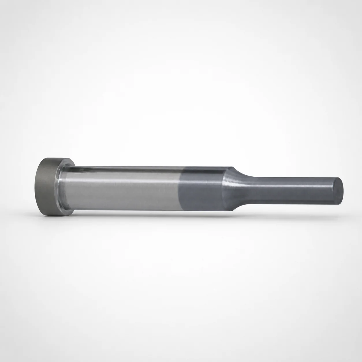
HW Coating Single-Stepped Shoulder Punches
HW coating single-stepped shoulder punches (HW coated) are engineered for reliable punch guidance and stable contact during die operation. The single-stepped shank geometry supports repeatable positioning in press tooling.
- Single-stepped shank for consistent seating and punch alignment
- HW coating increases surface durability for wear-prone forming cycles
- Designed for tight punch-to-holder fit using precision-ready dimensions
- Commonly used in die sets, punching stations, and mass production tooling
Specifications
5966 configurations available
| Tip shape | Material | Shank diameter D tolerance | B (Tip length) | D (Shank diameter) (mm) | P (Tip dimension) (mm) | L (L dimension) (mm) | LC (Full length alteration) (mm) | LCT (Head thickness tolerance change + total length alteration) (mm) | LMT (Head thickness tolerance change + Total length alteration) (mm) | PC (Tip dimension alteration) (mm) | R (Tip corner R) (mm) | W (Tip dimension) (mm) | WC (Tip dimension alteration) (mm) | type |
|---|---|---|---|---|---|---|---|---|---|---|---|---|---|---|
| Round | SKH40 Equivalent (Powdered High-Speed Steel) | +0.005/0 | L | 3 | 1 ~ 2.99 | 50 ~ 100 | - | - | - | - | - | - | - | - |
| Round | SKH40 Equivalent (Powdered High-Speed Steel) | +0.005/0 | L | 3 | 1 ~ 2.99 | - | 27 ~ 99.9 | - | - | - | - | - | - | - |
| Round | SKH40 Equivalent (Powdered High-Speed Steel) | +0.005/0 | L | 3 | 1 ~ 2.99 | - | - | 27 ~ 99.9 | - | - | - | - | - | - |
| Round | SKH40 Equivalent (Powdered High-Speed Steel) | +0.005/0 | L | 3 | 1 ~ 2.99 | - | - | - | 27 ~ 99.9 | - | - | - | - | - |
| Round | SKH40 Equivalent (Powdered High-Speed Steel) | +0.005/0 | L | 4 | 1 ~ 3.99 | 50 ~ 100 | - | - | - | - | - | - | - | - |
| Round | SKH40 Equivalent (Powdered High-Speed Steel) | +0.005/0 | L | 4 | - | 50 ~ 100 | - | - | - | 0.7 ~ 0.99 | - | - | - | - |
| Round | SKH40 Equivalent (Powdered High-Speed Steel) | +0.005/0 | L | 4 | 1 ~ 3.99 | - | 27 ~ 99.9 | - | - | - | - | - | - | - |
| Round | SKH40 Equivalent (Powdered High-Speed Steel) | +0.005/0 | L | 4 | - | - | 27 ~ 99.9 | - | - | 0.7 ~ 0.99 | - | - | - | - |
| Round | SKH40 Equivalent (Powdered High-Speed Steel) | +0.005/0 | L | 4 | 1 ~ 3.99 | - | - | 27 ~ 99.9 | - | - | - | - | - | - |
| Round | SKH40 Equivalent (Powdered High-Speed Steel) | +0.005/0 | L | 4 | - | - | - | 27 ~ 99.9 | - | 0.7 ~ 0.99 | - | - | - | - |
| Round | SKH40 Equivalent (Powdered High-Speed Steel) | +0.005/0 | L | 4 | 1 ~ 3.99 | - | - | - | 27 ~ 99.9 | - | - | - | - | - |
| Round | SKH40 Equivalent (Powdered High-Speed Steel) | +0.005/0 | L | 4 | - | - | - | - | 27 ~ 99.9 | 0.7 ~ 0.99 | - | - | - | - |
| Round | SKH40 Equivalent (Powdered High-Speed Steel) | +0.005/0 | L | 5 | 2 ~ 4.99 | 50 ~ 100 | - | - | - | - | - | - | - | - |
| Round | SKH40 Equivalent (Powdered High-Speed Steel) | +0.005/0 | L | 5 | - | 50 ~ 100 | - | - | - | 1 ~ 1.99 | - | - | - | - |
| Round | SKH40 Equivalent (Powdered High-Speed Steel) | +0.005/0 | L | 5 | 2 ~ 4.99 | - | 27 ~ 99.9 | - | - | - | - | - | - | - |
| Round | SKH40 Equivalent (Powdered High-Speed Steel) | +0.005/0 | L | 5 | - | - | 27 ~ 99.9 | - | - | 1 ~ 1.99 | - | - | - | - |
| Round | SKH40 Equivalent (Powdered High-Speed Steel) | +0.005/0 | L | 5 | 2 ~ 4.99 | - | - | 27 ~ 99.9 | - | - | - | - | - | - |
| Round | SKH40 Equivalent (Powdered High-Speed Steel) | +0.005/0 | L | 5 | - | - | - | 27 ~ 99.9 | - | 1 ~ 1.99 | - | - | - | - |
| Round | SKH40 Equivalent (Powdered High-Speed Steel) | +0.005/0 | L | 5 | 2 ~ 4.99 | - | - | - | 27 ~ 99.9 | - | - | - | - | - |
| Round | SKH40 Equivalent (Powdered High-Speed Steel) | +0.005/0 | L | 5 | - | - | - | - | 27 ~ 99.9 | 1 ~ 1.99 | - | - | - | - |
| Round | SKH40 Equivalent (Powdered High-Speed Steel) | +0.005/0 | L | 6 | 2 ~ 5.99 | 50 ~ 100 | - | - | - | - | - | - | - | - |
| Round | SKH40 Equivalent (Powdered High-Speed Steel) | +0.005/0 | L | 6 | - | 50 ~ 100 | - | - | - | 1 ~ 1.99 | - | - | - | - |
| Round | SKH40 Equivalent (Powdered High-Speed Steel) | +0.005/0 | L | 6 | 2 ~ 5.99 | - | 27 ~ 99.9 | - | - | - | - | - | - | - |
| Round | SKH40 Equivalent (Powdered High-Speed Steel) | +0.005/0 | L | 6 | - | - | 27 ~ 99.9 | - | - | 1 ~ 1.99 | - | - | - | - |
| Round | SKH40 Equivalent (Powdered High-Speed Steel) | +0.005/0 | L | 6 | 2 ~ 5.99 | - | - | 27 ~ 99.9 | - | - | - | - | - | - |
| Round | SKH40 Equivalent (Powdered High-Speed Steel) | +0.005/0 | L | 6 | - | - | - | 27 ~ 99.9 | - | 1 ~ 1.99 | - | - | - | - |
| Round | SKH40 Equivalent (Powdered High-Speed Steel) | +0.005/0 | L | 6 | 2 ~ 5.99 | - | - | - | 27 ~ 99.9 | - | - | - | - | - |
| Round | SKH40 Equivalent (Powdered High-Speed Steel) | +0.005/0 | L | 6 | - | - | - | - | 27 ~ 99.9 | 1 ~ 1.99 | - | - | - | - |
| Round | SKH40 Equivalent (Powdered High-Speed Steel) | +0.005/0 | L | 8 | 3 ~ 7.99 | 50 ~ 100 | - | - | - | - | - | - | - | - |
| Round | SKH40 Equivalent (Powdered High-Speed Steel) | +0.005/0 | L | 8 | - | 50 ~ 100 | - | - | - | 1.5 ~ 2.99 | - | - | - | - |
| Round | SKH40 Equivalent (Powdered High-Speed Steel) | +0.005/0 | L | 8 | 3 ~ 7.99 | - | 27 ~ 99.9 | - | - | - | - | - | - | - |
| Round | SKH40 Equivalent (Powdered High-Speed Steel) | +0.005/0 | L | 8 | - | - | 27 ~ 99.9 | - | - | 1.5 ~ 2.99 | - | - | - | - |
| Round | SKH40 Equivalent (Powdered High-Speed Steel) | +0.005/0 | L | 8 | 3 ~ 7.99 | - | - | 27 ~ 99.9 | - | - | - | - | - | - |
| Round | SKH40 Equivalent (Powdered High-Speed Steel) | +0.005/0 | L | 8 | - | - | - | 27 ~ 99.9 | - | 1.5 ~ 2.99 | - | - | - | - |
| Round | SKH40 Equivalent (Powdered High-Speed Steel) | +0.005/0 | L | 8 | 3 ~ 7.99 | - | - | - | 27 ~ 99.9 | - | - | - | - | - |
| Round | SKH40 Equivalent (Powdered High-Speed Steel) | +0.005/0 | L | 8 | - | - | - | - | 27 ~ 99.9 | 1.5 ~ 2.99 | - | - | - | - |
| Round | SKH40 Equivalent (Powdered High-Speed Steel) | +0.005/0 | L | 10 | 3 ~ 9.99 | 50 ~ 100 | - | - | - | - | - | - | - | - |
| Round | SKH40 Equivalent (Powdered High-Speed Steel) | +0.005/0 | L | 10 | - | 50 ~ 100 | - | - | - | 1.5 ~ 2.99 | - | - | - | - |
| Round | SKH40 Equivalent (Powdered High-Speed Steel) | +0.005/0 | L | 10 | 3 ~ 9.99 | - | 27 ~ 99.9 | - | - | - | - | - | - | - |
| Round | SKH40 Equivalent (Powdered High-Speed Steel) | +0.005/0 | L | 10 | - | - | 27 ~ 99.9 | - | - | 1.5 ~ 2.99 | - | - | - | - |
| Round | SKH40 Equivalent (Powdered High-Speed Steel) | +0.005/0 | L | 10 | 3 ~ 9.99 | - | - | 27 ~ 99.9 | - | - | - | - | - | - |
| Round | SKH40 Equivalent (Powdered High-Speed Steel) | +0.005/0 | L | 10 | - | - | - | 27 ~ 99.9 | - | 1.5 ~ 2.99 | - | - | - | - |
| Round | SKH40 Equivalent (Powdered High-Speed Steel) | +0.005/0 | L | 10 | 3 ~ 9.99 | - | - | - | 27 ~ 99.9 | - | - | - | - | - |
| Round | SKH40 Equivalent (Powdered High-Speed Steel) | +0.005/0 | L | 10 | - | - | - | - | 27 ~ 99.9 | 1.5 ~ 2.99 | - | - | - | - |
| Round | SKH40 Equivalent (Powdered High-Speed Steel) | +0.005/0 | L | 13 | 6 ~ 12.99 | 50 ~ 100 | - | - | - | - | - | - | - | - |
| Round | SKH40 Equivalent (Powdered High-Speed Steel) | +0.005/0 | L | 13 | - | 50 ~ 100 | - | - | - | 3 ~ 5.99 | - | - | - | - |
| Round | SKH40 Equivalent (Powdered High-Speed Steel) | +0.005/0 | L | 13 | 6 ~ 12.99 | - | 27 ~ 99.9 | - | - | - | - | - | - | - |
| Round | SKH40 Equivalent (Powdered High-Speed Steel) | +0.005/0 | L | 13 | - | - | 27 ~ 99.9 | - | - | 3 ~ 5.99 | - | - | - | - |
| Round | SKH40 Equivalent (Powdered High-Speed Steel) | +0.005/0 | L | 13 | 6 ~ 12.99 | - | - | 27 ~ 99.9 | - | - | - | - | - | - |
| Round | SKH40 Equivalent (Powdered High-Speed Steel) | +0.005/0 | L | 13 | - | - | - | 27 ~ 99.9 | - | 3 ~ 5.99 | - | - | - | - |
Product Guide
Application Scenarios+
These HW-coated single-stepped shoulder punches are used in precision die sets where stable punch seating and repeatable alignment are critical. The single-stepped shank geometry helps lock the punch position against the holder, supporting consistent contact and guidance during each stroke.
- Automotive/industrial punching stations: Ideal for high-cycle forming and blanking where wear at the punch tip and guiding surfaces reduces dimensional stability. The HW coating improves surface durability for longer production runs.
- General die work and press tooling: Suitable for setups requiring reliable positioning and tight punch-to-holder fit, helping maintain process repeatability across batches.
- Mass production components: The shoulder-based seating supports uniform engagement, reducing variation caused by seating drift over time.
Select this variant when you need both consistent seating (single step) and improved wear resistance in punch and press tooling environments.
Material & Process Details+
Available materials include SKH40 equivalent (powdered high-speed steel) and SKH51 equivalent (M2). Both are high-speed steels suitable for punching and forming due to their balance of hardness and toughness, but their wear performance can differ by grade.
- SKH51 (M2 equivalent): Typically selected for higher wear resistance in abrasive or high-load cycles, with a hardness commonly around HRC 61–63 after proper heat treatment.
- SKH40 equivalent: Often chosen when toughness and cutting/punching performance are balanced for die work demanding reliable behavior across varying cycle loads.
After machining, punches are generally quenched and tempered to achieve the target HRC, then finished to final dimensions. For wear-prone service, HW coating adds an additional surface durability layer, improving resistance at the guidance and tip regions while maintaining the steel’s core toughness.
Sizing & Selection Guide+
To select the correct punch size, start with the shank diameter D and the tip dimension matching your die opening and cutting geometry. This range supports D = 3 ~ 25 mm, with a shank diameter tolerance of +0.005/0, m5 for controlled fit in the holder.
- Tip geometry: Choose tip shape (round, rectangle, oblong, double flatted round, radius rectangle) and match P = 1 ~ 18 mm, plus W = 1 ~ 6 mm and corner radius R = 0.05 ~ 0.15 mm where applicable.
- Length matching: Select the appropriate L range (examples: 40–100, 50–100, 60–100, and others provided) to ensure full engagement and proper seating in your punch holder.
- Full length alteration: Use LC, LCT, LMT = 27 ~ 70.1 mm to align total length changes to your die set stack-up.
Because the shank is m5-rated, verify holder bore and seating design so the controlled diameter tolerance supports consistent guidance without excessive clearance.
Frequently Asked Questions
Which tip shapes and corner radii ranges are supported for these HW-coated single-stepped shoulder punches?+
How do I choose the shank diameter D and ensure proper punch-to-holder fit?+
What dimensional parameters control seating and total length when aligning the punch to a die set?+
Between SKH51 (M2 equivalent) and SKH40 equivalent, which is better for wear-prone punching cycles?+
How should I interpret tip dimension alteration values (PC, WC) when verifying final manufactured dimensions?+
Related Products






Need Custom Specifications?
Our engineering team can help with custom configurations, material selection, and volume pricing.