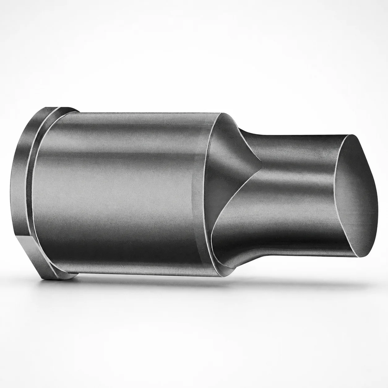
CRN Coated Extended Range Ejector Punches - Metric
Extended Range ejector punches (Metric) are CRN coated to support consistent ejection performance in tooling. The extended range geometry helps maintain alignment for reliable punch stroke and part release.
- CRN coating for improved wear resistance during repeated punching cycles
- Extended range punch profile helps stabilize ejection in die sets
- Available tip shapes (X, R, K, O, H, J, N, V, Y, Z) for application fit
- Metric configuration suitable for progressive and transfer die applications
Specifications
50 configurations available
| Tip shape | D (Shank dia.) (mm) | L1 (Point Length) (mm) | L (Length) (mm) | P Dimension (mm) | W Dimension (mm) | R Dimension (mm) |
|---|---|---|---|---|---|---|
| H | 40 | 25 ~ 30 | 63 ~ 100 | 20 ~ 39.95 | 8 ~ 39.95 | - |
| H | 45 | 25 ~ 30 | 63 ~ 100 | 25 ~ 44.95 | 9 ~ 44.95 | - |
| H | 50 | 25 ~ 30 | 63 ~ 100 | 30 ~ 49.95 | 10 ~ 49.95 | - |
| H | 56 | 25 ~ 30 | 63 ~ 100 | 35 ~ 55.95 | 11 ~ 55.95 | - |
| H | 63 | 25 ~ 30 | 63 ~ 100 | 40 ~ 62.95 | 12 ~ 62.95 | - |
| J | 40 | 25 ~ 30 | 63 ~ 100 | 20 ~ 39.95 | 8 ~ 39.95 | - |
| J | 45 | 25 ~ 30 | 63 ~ 100 | 25 ~ 44.95 | 9 ~ 44.95 | - |
| J | 50 | 25 ~ 30 | 63 ~ 100 | 30 ~ 49.95 | 10 ~ 49.95 | - |
| J | 56 | 25 ~ 30 | 63 ~ 100 | 35 ~ 55.95 | 11 ~ 55.95 | - |
| J | 63 | 25 ~ 30 | 63 ~ 100 | 40 ~ 62.95 | 12 ~ 62.95 | - |
| K | 40 | 25 ~ 30 | 63 ~ 100 | 20 ~ 39.95 | 8 ~ 39.95 | 0.2 ~ 19.975 |
| K | 45 | 25 ~ 30 | 63 ~ 100 | 25 ~ 44.95 | 9 ~ 44.95 | 0.2 ~ 22.475 |
| K | 50 | 25 ~ 30 | 63 ~ 100 | 30 ~ 49.95 | 10 ~ 49.95 | 0.2 ~ 24.975 |
| K | 56 | 25 ~ 30 | 63 ~ 100 | 35 ~ 55.95 | 11 ~ 55.95 | 0.2 ~ 27.975 |
| K | 63 | 25 ~ 30 | 63 ~ 100 | 40 ~ 62.95 | 12 ~ 62.95 | 0.2 ~ 31.475 |
| N | 40 | 25 ~ 30 | 63 ~ 100 | - | 8 ~ 39.95 | - |
| N | 45 | 25 ~ 30 | 63 ~ 100 | - | 9 ~ 44.95 | - |
| N | 50 | 25 ~ 30 | 63 ~ 100 | - | 10 ~ 49.95 | - |
| N | 56 | 25 ~ 30 | 63 ~ 100 | - | 11 ~ 55.95 | - |
| N | 63 | 25 ~ 30 | 63 ~ 100 | - | 12 ~ 62.95 | - |
| O | 40 | 25 ~ 30 | 63 ~ 100 | 20 ~ 39.95 | 8 ~ 39.95 | - |
| O | 45 | 25 ~ 30 | 63 ~ 100 | 25 ~ 44.95 | 9 ~ 44.95 | - |
| O | 50 | 25 ~ 30 | 63 ~ 100 | 30 ~ 49.95 | 10 ~ 49.95 | - |
| O | 56 | 25 ~ 30 | 63 ~ 100 | 35 ~ 55.95 | 11 ~ 55.95 | - |
| O | 63 | 25 ~ 30 | 63 ~ 100 | 40 ~ 62.95 | 12 ~ 62.95 | - |
| R | 40 | 25 ~ 30 | 63 ~ 100 | 20 ~ 39.95 | 8 ~ 39.95 | - |
| R | 45 | 25 ~ 30 | 63 ~ 100 | 25 ~ 44.95 | 9 ~ 44.95 | - |
| R | 50 | 25 ~ 30 | 63 ~ 100 | 30 ~ 49.95 | 10 ~ 49.95 | - |
| R | 56 | 25 ~ 30 | 63 ~ 100 | 35 ~ 55.95 | 11 ~ 55.95 | - |
| R | 63 | 25 ~ 30 | 63 ~ 100 | 40 ~ 62.95 | 12 ~ 62.95 | - |
| V | 40 | 25 ~ 30 | 63 ~ 100 | 20 ~ 39.95 | 8 ~ 39.95 | - |
| V | 45 | 25 ~ 30 | 63 ~ 100 | 25 ~ 44.95 | 9 ~ 44.95 | - |
| V | 50 | 25 ~ 30 | 63 ~ 100 | 30 ~ 49.95 | 10 ~ 49.95 | - |
| V | 56 | 25 ~ 30 | 63 ~ 100 | 35 ~ 55.95 | 11 ~ 55.95 | - |
| V | 63 | 25 ~ 30 | 63 ~ 100 | 40 ~ 62.95 | 12 ~ 62.95 | - |
| X | 40 | 25 ~ 30 | 63 ~ 100 | 20 ~ 39.95 | - | - |
| X | 45 | 25 ~ 30 | 63 ~ 100 | 25 ~ 44.95 | - | - |
| X | 50 | 25 ~ 30 | 63 ~ 100 | 30 ~ 49.95 | - | - |
| X | 56 | 25 ~ 30 | 63 ~ 100 | 35 ~ 55.95 | - | - |
| X | 63 | 25 ~ 30 | 63 ~ 100 | 40 ~ 62.95 | - | - |
| Y | 40 | 25 ~ 30 | 63 ~ 100 | 20 ~ 39.95 | 8 ~ 39.95 | 0.2 ~ 19.975 |
| Y | 45 | 25 ~ 30 | 63 ~ 100 | 25 ~ 44.95 | 9 ~ 44.95 | 0.2 ~ 22.475 |
| Y | 50 | 25 ~ 30 | 63 ~ 100 | 30 ~ 49.95 | 10 ~ 49.95 | 0.2 ~ 24.975 |
| Y | 56 | 25 ~ 30 | 63 ~ 100 | 35 ~ 55.95 | 11 ~ 55.95 | 0.2 ~ 27.975 |
| Y | 63 | 25 ~ 30 | 63 ~ 100 | 40 ~ 62.95 | 12 ~ 62.95 | 0.2 ~ 31.475 |
| Z | 40 | 25 ~ 30 | 63 ~ 100 | - | 8 ~ 39.95 | 0.2 ~ 19.975 |
| Z | 45 | 25 ~ 30 | 63 ~ 100 | - | 9 ~ 44.95 | 0.2 ~ 22.475 |
| Z | 50 | 25 ~ 30 | 63 ~ 100 | - | 10 ~ 49.95 | 0.2 ~ 24.975 |
| Z | 56 | 25 ~ 30 | 63 ~ 100 | - | 11 ~ 55.95 | 0.2 ~ 27.975 |
| Z | 63 | 25 ~ 30 | 63 ~ 100 | - | 12 ~ 62.95 | 0.2 ~ 31.475 |
Product Guide
Application Scenarios+
These CRN coated extended range ejector punches are used in progressive and transfer die tooling where consistent part release must be maintained over many repeated strokes. The extended range geometry supports stable alignment through the die set, helping reduce side loading and ejection inconsistency.
- Automotive and appliance progressive dies: For ejecting small stamped components after forming operations, the CRN coating improves wear behavior, supporting repeatable ejection timing across production runs.
- Electronic connector/terminal forming lines: When parts must clear tight die features, the controlled point length (L1 25–30 mm) and longer overall reach (L 63–100 mm) help maintain punch guidance during the stroke.
- Multi-station transfer dies: Extended range punches help maintain punch posture through longer die stacks; select compatible tip shapes (H, J, K, N, O, R, V, X, Y, Z) to match specific part undercuts and contact requirements.
Choose this variant when you need both alignment stability and wear resistance to protect ejection performance in high-cycle tooling.
Material & Process Details+
The provided specification confirms a CRN (Chromium Nitride) coated ejector punch configuration, intended to enhance wear resistance during repeated punching cycles. While the base steel grade and exact heat-treatment state are not included in the input data, the CRN coating is selected to withstand abrasion and frictional contact typical of ejector action.
- Coating function: Improves surface durability and helps maintain dimensional stability and ejection consistency as cycle counts increase.
- Hardness & trade-off: CRN coatings generally increase surface hardness and abrasion resistance; the performance benefit is realized alongside the underlying toughness of the punch substrate (exact HRC not specified in the data).
- Heat treatment: Not specified; however, the finished punches are supplied as a coated product variant suitable for die service where wear is a primary driver.
If you need a particular substrate hardness/toughness balance for shock loading, confirm the base steel grade and HRC with your Axiom Molds representative for your application requirements.
Sizing & Selection Guide+
To select the correct extended range ejector punch, match the overall reach and point engagement to your die cavity/core clearance and ejection stroke requirements. This series offers overall length L of 63–100 mm and a point length L1 fixed at 25–30 mm.
- Choose shank diameter D: Select one of 40, 45, 50, 56, or 63 mm to correspond with your punch guide/holder bore sizing and desired guidance stiffness.
- Match engagement features (P and W): Use the available P ranges (20–39.95, 25–44.95, 30–49.95, 35–55.95, 40–62.95 mm) and W ranges (8–39.95, 9–44.95, 10–49.95, 11–55.95, 12–62.95 mm) to fit the part geometry and the expected contact zone during ejection.
- Verify point form (R): Select the specified R range (0.2–19.975 up to 0.2–31.475) to control the radius at the working tip.
Tip shape (H, J, K, N, O, R, V, X, Y, Z) is variable; use it to match the part’s undercut/edge profile. For final fit, confirm your die punch guide and holder tolerances—coated surfaces can affect clearance if you run very tight guidance.
Frequently Asked Questions
Which tip shapes are available for CRN coated extended range ejector punches in this metric series?+
How do I choose the extended range length L and point length L1 for my die stack height?+
What shank diameters D are offered, and how do they relate to guidance in progressive/transfer dies?+
What do the P, W, and R dimensions control on the ejector punch profile?+
Does the CRN coating replace the need to specify base steel hardness and heat treatment?+
Related Products






Need Custom Specifications?
Our engineering team can help with custom configurations, material selection, and volume pricing.