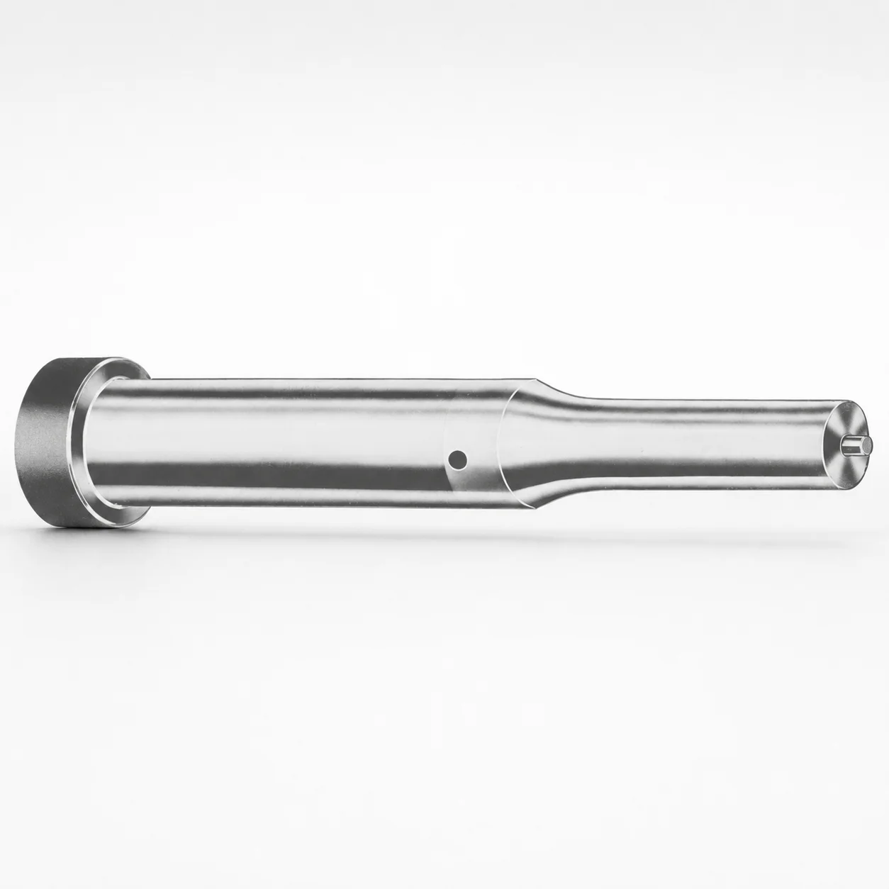
Metric Ejector Punches XNA Coating
Metric ejector punches with XNA coating provide stable punch ejection for die maintenance cycles, helping reduce galling and wear during repeated forming operations. Optimized for metric punch tooling needs.
- Coating system: XNA coating to enhance surface durability
- Metric ejector punch style designed for consistent ejection alignment
- Supports multiple tip geometries for tooling-specific performance
- Built for industrial die applications where wear control matters
Specifications
367 configurations available
| Tip shape | Material | D (Shank dia.) (mm) | Jektole group | L1 (Point Length) (mm) | L (Length) (mm) | P Dimension (mm) | W Dimension (mm) | R Dimension (mm) |
|---|---|---|---|---|---|---|---|---|
| H | M2 | 05 | J2M | 13 ~ 19 | 40 ~ 80 | 1.6 ~ 4.95 | 1.6 ~ 4.95 | - |
| H | PS | 05 | J2M | 13 ~ 19 | 40 ~ 80 | 1.6 ~ 4.95 | 1.6 ~ 4.95 | - |
| H | M2 | 06 | J3M | 13 ~ 19 | 40 ~ 100 | 2 ~ 5.95 | 2 ~ 2.39 | - |
| H | M2 | 06 | J3M | 13 ~ 19 | 40 ~ 100 | 2 ~ 5.95 | 2.4 ~ 5.95 | - |
| H | PS | 06 | J3M | 13 ~ 19 | 40 ~ 100 | 2 ~ 5.95 | 2 ~ 2.39 | - |
| H | PS | 06 | J3M | 13 ~ 19 | 40 ~ 100 | 2 ~ 5.95 | 2.4 ~ 5.95 | - |
| H | M2 | 08 | J4M | 19 ~ 25 | 50 ~ 100 | 3 ~ 7.95 | 3 ~ 3.19 | - |
| H | M2 | 08 | J4M | 19 ~ 25 | 50 ~ 100 | 3 ~ 7.95 | 3.2 ~ 7.95 | - |
| H | PS | 08 | J4M | 19 ~ 25 | 50 ~ 100 | 3 ~ 7.95 | 3 ~ 3.19 | - |
| H | PS | 08 | J4M | 19 ~ 25 | 50 ~ 100 | 3 ~ 7.95 | 3.2 ~ 7.95 | - |
| H | M2 | 10 | J6M | 19 ~ 25 | 50 ~ 100 | 4 ~ 9.95 | 4 ~ 4.49 | - |
| H | M2 | 10 | J6M | 19 ~ 25 | 50 ~ 100 | 4 ~ 9.95 | 4.5 ~ 9.95 | - |
| H | PS | 10 | J6M | 19 ~ 25 | 50 ~ 100 | 4 ~ 9.95 | 4 ~ 4.49 | - |
| H | PS | 10 | J6M | 19 ~ 25 | 50 ~ 100 | 4 ~ 9.95 | 4.5 ~ 9.95 | - |
| H | M2 | 13 | J6M | 19 ~ 25 | 50 ~ 100 | 4 ~ 12.95 | 4 ~ 5.99 | - |
| H | M2 | 13 | J6M | 19 ~ 25 | 50 ~ 100 | 4 ~ 12.95 | 6 ~ 12.95 | - |
| H | PS | 13 | J6M | 19 ~ 25 | 50 ~ 100 | 4 ~ 12.95 | 4 ~ 5.99 | - |
| H | PS | 13 | J6M | 19 ~ 25 | 50 ~ 100 | 4 ~ 12.95 | 6 ~ 12.95 | - |
| H | M2 | 16 | J9M | 19 ~ 25 | 50 ~ 100 | 6 ~ 15.95 | 6 ~ 7.19 | - |
| H | M2 | 16 | J9M | 19 ~ 25 | 50 ~ 100 | 6 ~ 15.95 | 7.2 ~ 15.95 | - |
| H | PS | 16 | J9M | 19 ~ 25 | 50 ~ 100 | 6 ~ 15.95 | 6 ~ 7.19 | - |
| H | PS | 16 | J9M | 19 ~ 25 | 50 ~ 100 | 6 ~ 15.95 | 7.2 ~ 15.95 | - |
| H | M2 | 20 | J9M | 19 ~ 25 | 50 ~ 100 | 6 ~ 19.95 | 6 ~ 7.99 | - |
| H | M2 | 20 | J9M | 19 ~ 25 | 50 ~ 100 | 6 ~ 19.95 | 8 ~ 19.95 | - |
| H | PS | 20 | J9M | 19 ~ 25 | 50 ~ 100 | 6 ~ 19.95 | 6 ~ 7.99 | - |
| H | PS | 20 | J9M | 19 ~ 25 | 50 ~ 100 | 6 ~ 19.95 | 8 ~ 19.95 | - |
| H | M2 | 25 | J9M | 19 ~ 25 | 50 ~ 100 | 6 ~ 24.95 | 6 ~ 8.99 | - |
| H | M2 | 25 | J9M | 19 ~ 25 | 50 ~ 100 | 6 ~ 24.95 | 9 ~ 24.95 | - |
| H | PS | 25 | J9M | 19 ~ 25 | 50 ~ 100 | 6 ~ 24.95 | 6 ~ 8.99 | - |
| H | PS | 25 | J9M | 19 ~ 25 | 50 ~ 100 | 6 ~ 24.95 | 9 ~ 24.95 | - |
| H | M2 | 32 | J12M | 25 ~ 30 | 63 ~ 100 | 7.2 ~ 31.95 | 7.2 ~ 9.99 | - |
| H | M2 | 32 | J12M | 25 ~ 30 | 63 ~ 100 | 7.2 ~ 31.95 | 10 ~ 31.95 | - |
| H | PS | 32 | J12M | 25 ~ 30 | 63 ~ 100 | 7.2 ~ 31.95 | 7.2 ~ 9.99 | - |
| H | PS | 32 | J12M | 25 ~ 30 | 63 ~ 100 | 7.2 ~ 31.95 | 10 ~ 31.95 | - |
| J | M2 | 05 | J2M | 13 ~ 19 | 40 ~ 80 | 1.6 ~ 4.95 | 1.6 ~ 4.95 | - |
| J | PS | 05 | J2M | 13 ~ 19 | 40 ~ 80 | 1.6 ~ 4.95 | 1.6 ~ 4.95 | - |
| J | M2 | 06 | J3M | 13 ~ 19 | 40 ~ 100 | 2 ~ 5.95 | 2 ~ 2.39 | - |
| J | M2 | 06 | J3M | 13 ~ 19 | 40 ~ 100 | 2 ~ 5.95 | 2.4 ~ 5.95 | - |
| J | PS | 06 | J3M | 13 ~ 19 | 40 ~ 100 | 2 ~ 5.95 | 2 ~ 2.39 | - |
| J | PS | 06 | J3M | 13 ~ 19 | 40 ~ 100 | 2 ~ 5.95 | 2.4 ~ 5.95 | - |
| J | M2 | 08 | J4M | 19 ~ 25 | 50 ~ 100 | 3 ~ 7.95 | 3 ~ 3.19 | - |
| J | M2 | 08 | J4M | 19 ~ 25 | 50 ~ 100 | 3 ~ 7.95 | 3.2 ~ 7.95 | - |
| J | PS | 08 | J4M | 19 ~ 25 | 50 ~ 100 | 3 ~ 7.95 | 3 ~ 3.19 | - |
| J | PS | 08 | J4M | 19 ~ 25 | 50 ~ 100 | 3 ~ 7.95 | 3.2 ~ 7.95 | - |
| J | M2 | 10 | J6M | 19 ~ 25 | 50 ~ 100 | 4 ~ 9.95 | 4 ~ 4.49 | - |
| J | M2 | 10 | J6M | 19 ~ 25 | 50 ~ 100 | 4 ~ 9.95 | 4.5 ~ 9.95 | - |
| J | PS | 10 | J6M | 19 ~ 25 | 50 ~ 100 | 4 ~ 9.95 | 4 ~ 4.49 | - |
| J | PS | 10 | J6M | 19 ~ 25 | 50 ~ 100 | 4 ~ 9.95 | 4.5 ~ 9.95 | - |
| J | M2 | 13 | J6M | 19 ~ 25 | 50 ~ 100 | 4 ~ 12.95 | 4 ~ 5.99 | - |
| J | M2 | 13 | J6M | 19 ~ 25 | 50 ~ 100 | 4 ~ 12.95 | 6 ~ 12.95 | - |
Product Guide
Application Scenarios+
Metric ejector punches with an XNA coating are used in injection and forming tooling where repeatable part expulsion directly affects die life and dimensional consistency. The XNA surface is suited for automotive connector and bracket mold inserts, helping limit galling and abrasion on punch tips during frequent ejection cycles.
They are also a strong fit for appliance and consumer goods die sets that run at higher duty cycles, because the punch-and-die interface benefits from improved surface durability rather than relying solely on base hardness.
For medical device housing or precision components, stable ejection alignment reduces scuffing risk on fine features. Choose from the available tip shapes (H, J, K, L, N, O, R, V, X, Y, Z) to match the required contact geometry, and select the appropriate shank diameter (D = 5–32 mm) and length (L = 40–100 mm, depending on configuration) for your cavity/core layout.
Material & Process Details+
This series is offered in M2 and PS base materials, selected to balance wear resistance and toughness for punch/die contact. While exact heat-treatment targets are not provided in the listing, M2 is commonly used as a high-speed steel with good hot-spot abrasion resistance; PS is typically chosen when a different toughness-to-wear balance is preferred for forming dies and ejector interfaces.
- M2: higher wear resistance tendency; best for applications where abrasive wear and repeated ejection justify a harder, wear-focused base.
- PS: alternative steel selection for tooling needs where toughness or machining behavior is prioritized alongside wear control.
- XNA coating: applied as a surface durability layer to reduce galling and improve service life at the contact zone.
Hardness (HRC) values are not specified in the provided data; final hardness is typically achieved via the supplier’s standard steel heat treatment for the selected grade prior to coating, with performance governed by both base steel condition and the XNA layer.
Sizing & Selection Guide+
Correct sizing starts with matching the ejector punch to the die layout and the required point contact. Use the provided ranges to select the shank diameter (D = 5–32 mm) first, ensuring it fits the ejector guide and the mating bore without binding.
- Tip shape: pick the geometry (H, J, K, L, N, O, R, V, X, Y, Z) that matches your part contact area and prevents edge marking.
- Point length (L1): available as 13–19 mm, 19–25 mm, or 25–30 mm to control engagement depth at the cavity interface.
- P and W: select P = 1.3–16 mm and W = 1.6–10 mm to conform to your punch profile and supporting shoulder geometry.
Choose total length (L) from the available configurations (e.g., 40–80, 40–100, 50–100, or 63–100 mm) so the punch stroke reaches full ejection without overtravel. Tolerance/fit values are not provided here—apply standard die clearances for ejector guidance and ensure any interface tolerances are defined in your mold drawing.
Frequently Asked Questions
Which tip shape options (H, J, K, L, N, O, R, V, X, Y, Z) should I use for minimizing scuffing on ejector-contact surfaces?+
Select the tip shape based on your part’s contact area and the required engagement geometry. This series supports H, J, K, L, N, O, R, V, X, Y, Z, which allows you to tailor the point profile to reduce edge loading and improve surface contact consistency.
After choosing the tip shape, verify that L1 (13–19 / 19–25 / 25–30 mm) provides the correct engagement depth for the cavity/core thickness you are ejecting against.
How do I choose the correct ejector punch shank diameter D for my mold guide and bore dimensions?+
Use the available D (5–32 mm) range to match your ejector guide and the corresponding bore. Pick the diameter that provides the required clearance to avoid sticking during repeated cycling.
Because tolerance/fit values are not listed in the provided data, your mold drawing should define the final clearance and guidance requirements for reliable ejection.
What length should I specify (L and L1) to prevent under-ejection or overtravel in the die set?+
Set total length L from the provided options (40–80, 40–100, 50–100, or 63–100 mm) to align with your ejector stroke and die stacking.
Then select the point length L1 in 13–19, 19–25, or 25–30 mm to control engagement depth at the cavity interface.
What is the purpose of the XNA coating for ejector punches, and how does it affect wear and galling?+
The XNA coating is specified for improved surface durability at the punch/die contact. It is intended to reduce galling and wear during repeated forming operations.
Use the XNA-coated variant when your application experiences high ejection cycles or abrasive contact where base material alone may not provide sufficient long-term surface protection.
When should I select M2 versus PS material for this ejector punch series?+
This series lists Material: M2, PS as available options. Choose M2 when you prioritize wear resistance for punch/die interface performance under repeated ejection cycles.
Select PS when the tooling requirement calls for a different balance of properties versus M2, such as varying toughness-to-wear needs.
For final performance, confirm hardness and heat-treatment condition with the supplier’s standard for the selected grade, since HRC values are not included in the provided data.
Related Products






Need Custom Specifications?
Our engineering team can help with custom configurations, material selection, and volume pricing.