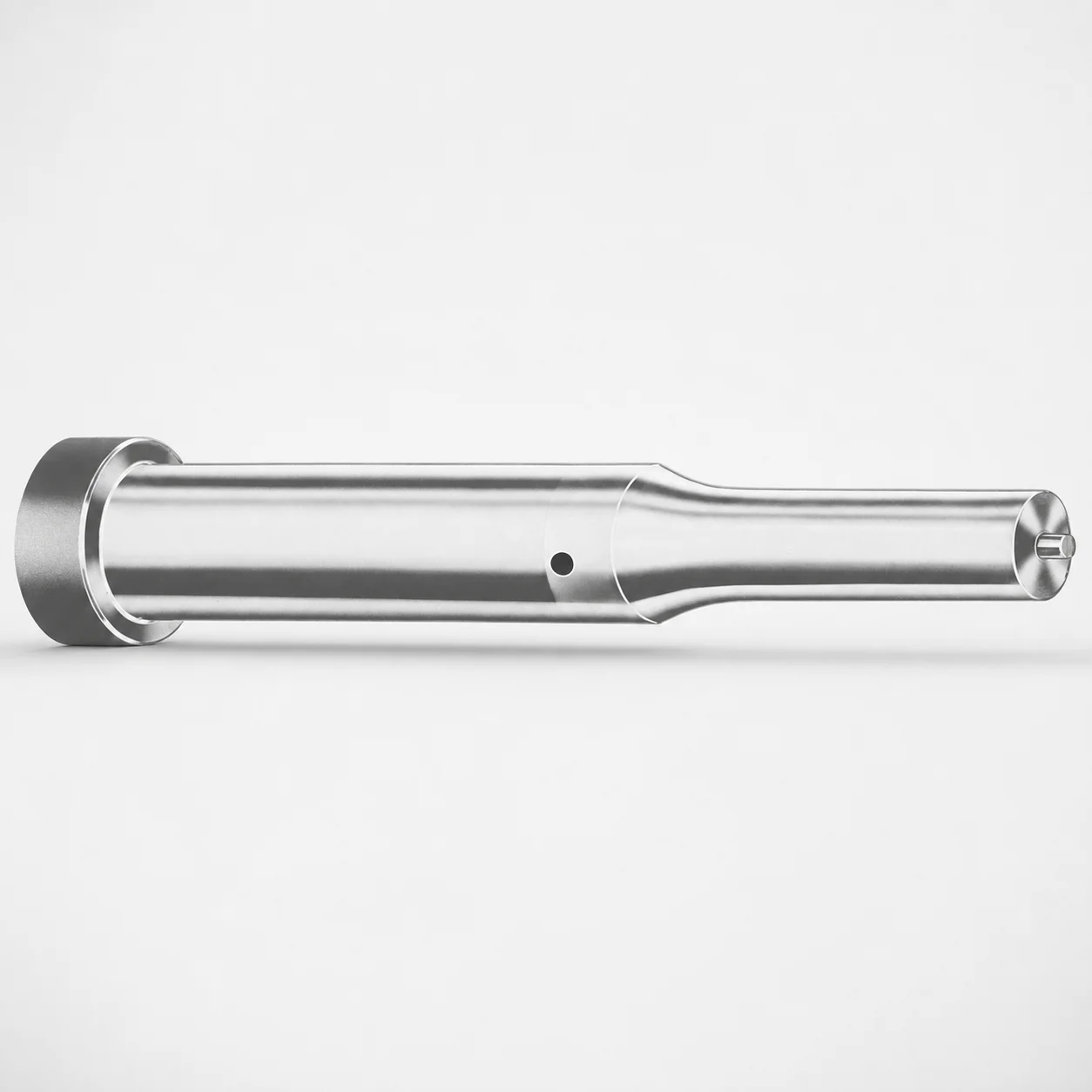
Metric Ejector Punches - XCD Coating
Metric ejector punches (XCD coating) are precision punch components for reliable part ejection in stamping, molding, and die-casting applications. The XCD coating supports smoother sliding and improved wear resistance in production.
- Metric punch format designed for consistent ejection behavior
- XCD coating helps reduce friction and wear during cycles
- Manufactured with controlled point and shank geometry for stable fit
- Commonly used in progressive dies and injection mold tooling
Specifications
367 configurations available
| Tip shape | Material | D (Shank dia.) (mm) | Jektole group | L1 (Point Length) (mm) | L (Length) (mm) | P Dimension (mm) | W Dimension (mm) | R Dimension (mm) |
|---|---|---|---|---|---|---|---|---|
| H | M2 | 05 | J2M | 13 ~ 19 | 40 ~ 80 | 1.6 ~ 4.95 | 1.6 ~ 4.95 | - |
| H | PS | 05 | J2M | 13 ~ 19 | 40 ~ 80 | 1.6 ~ 4.95 | 1.6 ~ 4.95 | - |
| H | M2 | 06 | J3M | 13 ~ 19 | 40 ~ 100 | 2 ~ 5.95 | 2 ~ 2.39 | - |
| H | M2 | 06 | J3M | 13 ~ 19 | 40 ~ 100 | 2 ~ 5.95 | 2.4 ~ 5.95 | - |
| H | PS | 06 | J3M | 13 ~ 19 | 40 ~ 100 | 2 ~ 5.95 | 2 ~ 2.39 | - |
| H | PS | 06 | J3M | 13 ~ 19 | 40 ~ 100 | 2 ~ 5.95 | 2.4 ~ 5.95 | - |
| H | M2 | 08 | J4M | 19 ~ 25 | 50 ~ 100 | 3 ~ 7.95 | 3 ~ 3.19 | - |
| H | M2 | 08 | J4M | 19 ~ 25 | 50 ~ 100 | 3 ~ 7.95 | 3.2 ~ 7.95 | - |
| H | PS | 08 | J4M | 19 ~ 25 | 50 ~ 100 | 3 ~ 7.95 | 3 ~ 3.19 | - |
| H | PS | 08 | J4M | 19 ~ 25 | 50 ~ 100 | 3 ~ 7.95 | 3.2 ~ 7.95 | - |
| H | M2 | 10 | J6M | 19 ~ 25 | 50 ~ 100 | 4 ~ 9.95 | 4 ~ 4.49 | - |
| H | M2 | 10 | J6M | 19 ~ 25 | 50 ~ 100 | 4 ~ 9.95 | 4.5 ~ 9.95 | - |
| H | PS | 10 | J6M | 19 ~ 25 | 50 ~ 100 | 4 ~ 9.95 | 4 ~ 4.49 | - |
| H | PS | 10 | J6M | 19 ~ 25 | 50 ~ 100 | 4 ~ 9.95 | 4.5 ~ 9.95 | - |
| H | M2 | 13 | J6M | 19 ~ 25 | 50 ~ 100 | 4 ~ 12.95 | 4 ~ 5.99 | - |
| H | M2 | 13 | J6M | 19 ~ 25 | 50 ~ 100 | 4 ~ 12.95 | 6 ~ 12.95 | - |
| H | PS | 13 | J6M | 19 ~ 25 | 50 ~ 100 | 4 ~ 12.95 | 4 ~ 5.99 | - |
| H | PS | 13 | J6M | 19 ~ 25 | 50 ~ 100 | 4 ~ 12.95 | 6 ~ 12.95 | - |
| H | M2 | 16 | J9M | 19 ~ 25 | 50 ~ 100 | 6 ~ 15.95 | 6 ~ 7.19 | - |
| H | M2 | 16 | J9M | 19 ~ 25 | 50 ~ 100 | 6 ~ 15.95 | 7.2 ~ 15.95 | - |
| H | PS | 16 | J9M | 19 ~ 25 | 50 ~ 100 | 6 ~ 15.95 | 6 ~ 7.19 | - |
| H | PS | 16 | J9M | 19 ~ 25 | 50 ~ 100 | 6 ~ 15.95 | 7.2 ~ 15.95 | - |
| H | M2 | 20 | J9M | 19 ~ 25 | 50 ~ 100 | 6 ~ 19.95 | 6 ~ 7.99 | - |
| H | M2 | 20 | J9M | 19 ~ 25 | 50 ~ 100 | 6 ~ 19.95 | 8 ~ 19.95 | - |
| H | PS | 20 | J9M | 19 ~ 25 | 50 ~ 100 | 6 ~ 19.95 | 6 ~ 7.99 | - |
| H | PS | 20 | J9M | 19 ~ 25 | 50 ~ 100 | 6 ~ 19.95 | 8 ~ 19.95 | - |
| H | M2 | 25 | J9M | 19 ~ 25 | 50 ~ 100 | 6 ~ 24.95 | 6 ~ 8.99 | - |
| H | M2 | 25 | J9M | 19 ~ 25 | 50 ~ 100 | 6 ~ 24.95 | 9 ~ 24.95 | - |
| H | PS | 25 | J9M | 19 ~ 25 | 50 ~ 100 | 6 ~ 24.95 | 6 ~ 8.99 | - |
| H | PS | 25 | J9M | 19 ~ 25 | 50 ~ 100 | 6 ~ 24.95 | 9 ~ 24.95 | - |
| H | M2 | 32 | J12M | 25 ~ 30 | 63 ~ 100 | 7.2 ~ 31.95 | 7.2 ~ 9.99 | - |
| H | M2 | 32 | J12M | 25 ~ 30 | 63 ~ 100 | 7.2 ~ 31.95 | 10 ~ 31.95 | - |
| H | PS | 32 | J12M | 25 ~ 30 | 63 ~ 100 | 7.2 ~ 31.95 | 7.2 ~ 9.99 | - |
| H | PS | 32 | J12M | 25 ~ 30 | 63 ~ 100 | 7.2 ~ 31.95 | 10 ~ 31.95 | - |
| J | M2 | 05 | J2M | 13 ~ 19 | 40 ~ 80 | 1.6 ~ 4.95 | 1.6 ~ 4.95 | - |
| J | PS | 05 | J2M | 13 ~ 19 | 40 ~ 80 | 1.6 ~ 4.95 | 1.6 ~ 4.95 | - |
| J | M2 | 06 | J3M | 13 ~ 19 | 40 ~ 100 | 2 ~ 5.95 | 2 ~ 2.39 | - |
| J | M2 | 06 | J3M | 13 ~ 19 | 40 ~ 100 | 2 ~ 5.95 | 2.4 ~ 5.95 | - |
| J | PS | 06 | J3M | 13 ~ 19 | 40 ~ 100 | 2 ~ 5.95 | 2 ~ 2.39 | - |
| J | PS | 06 | J3M | 13 ~ 19 | 40 ~ 100 | 2 ~ 5.95 | 2.4 ~ 5.95 | - |
| J | M2 | 08 | J4M | 19 ~ 25 | 50 ~ 100 | 3 ~ 7.95 | 3 ~ 3.19 | - |
| J | M2 | 08 | J4M | 19 ~ 25 | 50 ~ 100 | 3 ~ 7.95 | 3.2 ~ 7.95 | - |
| J | PS | 08 | J4M | 19 ~ 25 | 50 ~ 100 | 3 ~ 7.95 | 3 ~ 3.19 | - |
| J | PS | 08 | J4M | 19 ~ 25 | 50 ~ 100 | 3 ~ 7.95 | 3.2 ~ 7.95 | - |
| J | M2 | 10 | J6M | 19 ~ 25 | 50 ~ 100 | 4 ~ 9.95 | 4 ~ 4.49 | - |
| J | M2 | 10 | J6M | 19 ~ 25 | 50 ~ 100 | 4 ~ 9.95 | 4.5 ~ 9.95 | - |
| J | PS | 10 | J6M | 19 ~ 25 | 50 ~ 100 | 4 ~ 9.95 | 4 ~ 4.49 | - |
| J | PS | 10 | J6M | 19 ~ 25 | 50 ~ 100 | 4 ~ 9.95 | 4.5 ~ 9.95 | - |
| J | M2 | 13 | J6M | 19 ~ 25 | 50 ~ 100 | 4 ~ 12.95 | 4 ~ 5.99 | - |
| J | M2 | 13 | J6M | 19 ~ 25 | 50 ~ 100 | 4 ~ 12.95 | 6 ~ 12.95 | - |
Product Guide
Application Scenarios+
These metric ejector punches are used in injection mold tooling and die-casting systems where stable, repeatable ejection force is critical. The XCD coating variant is suited for applications that run high cycle counts, helping the punch slide more smoothly and resist wear at the guided interface.
- Automotive and appliance molding inserts: Use the selected tip shape (H/J/K/L/N/O/R/V/X/Y/Z) to match part geometry and ejector pin access, while the robust punch geometry supports consistent ejection behavior across production runs.
- Die-casting ejector systems: The hardened steel option (M2 or PS) combined with XCD coating reduces friction and supports longer tool life in abrasive or thermally demanding casting environments.
- Progressive die and appliance stamping interfaces: The tight fit and controlled point/shank geometry improve alignment, reducing side load during strip or part ejection.
Choose this variant when you need controlled fit, stable ejection, and reduced wear from repeated sliding under load.
Material & Process Details+
This series is available in M2 or PS tool steel options, selected to balance wear resistance and toughness for ejector punch duties. M2 is typically chosen where higher wear resistance is required under frequent ejection cycles; it is commonly heat-treated by quenching and tempering to reach high hardness suitable for sliding components.
The exact hardness and heat-treatment state are not specified in the provided data, so verify at the time of quotation for your required wear/impact balance. In general, higher hardness improves abrasion resistance but can reduce toughness if excessively hard for the duty.
- M2 option: Prioritize wear resistance for long runs with higher sliding contact.
- PS option: Often selected when a toughness-oriented balance is preferred for demanding ejection conditions.
- XCD coating (series variant): Adds surface protection to help reduce friction and wear during cycling.
Sizing & Selection Guide+
Selection starts with the shank diameter D and overall length needed to reach the ejector stroke while remaining fully supported in the mold’s guide system. For this series, D is 5–32 mm, and L is available across ranges: 40–80, 40–100, 50–100, or 63–100 mm.
- Match shank fit: Choose the D size that corresponds to your ejector guide bore/leader clearance design. Because only D ranges are provided (no tolerance values), confirm the final fit class during engineering review.
- Point reach and clearance: Select L1 (point length) from 13–19, 19–25, or 25–30 mm to ensure correct contact with the part while avoiding interference.
- Geometry match: Pick the required tip shape (H/J/K/L/N/O/R/V/X/Y/Z) and supporting dimensions P (1.3–16 mm), W (1.6–10 mm), and R (0.2 mm) to suit your part ejector interface.
- Other grouping: The Jektole group (e.g., J2M/J3M/J4M/J6M/J9M/J12M) should be aligned to your die/mold standardization.
Some dimensions are fixed to the available ranges, so order the configuration that most closely fits cavity/core and ejector assembly constraints, then confirm clearances and retention features against your drawing.
Frequently Asked Questions
Which tip shapes (H/J/K/L/N/O/R/V/X/Y/Z) should I choose for an ejector punch to match my part geometry?+
Tip shape selection should follow the part contact area and ejector clearance envelope. This series offers multiple tip shapes (H, J, K, L, N, O, R, V, X, Y, Z), allowing you to align the point profile with the part’s underside and ejector access.
Once the tip profile is chosen, verify L1 (13–19, 19–25, or 25–30 mm) so the point length reaches the correct contact zone without interference.
How do I choose the correct shank diameter D and overall length L for stable guide fit?+
Select D (5–32 mm) to match your ejector guide bore/leader design in the mold. Then choose L from the available ranges (40–80, 40–100, 50–100, or 63–100 mm) to ensure the punch is fully supported throughout the ejector stroke.
No tolerance values are provided in the data, so confirm the final fit/clearance requirements with your guide system specification during engineering review.
What is the role of XCD coating in die-casting and high-cycle molding ejector systems?+
The XCD coating variant is intended to reduce sliding friction at the guided interface and improve wear behavior during repeated ejection cycles.
In die-casting and high-cycle molding, this helps maintain stable ejection and supports longer service life compared with uncoated surfaces under abrasive or high-contact conditions.
Between M2 and PS steel options, how should I decide for wear versus toughness in ejector punching?+
This series provides M2 and PS material options. M2 is typically selected when higher wear resistance is the priority for frequent ejection cycles, while PS is often chosen to achieve a different balance that can favor toughness depending on heat treatment.
Because hardness and exact heat-treatment state are not specified here, confirm the heat-treatment and target hardness during quotation to match your load and cycle conditions.
How do P, W, and the R dimension affect punch compatibility with my ejector cavity/core design?+
These dimensions define the punch’s detailed interface geometry and should be matched to the contact and clearance requirements of your part and cavity/core. This series specifies P = 1.3–16 mm, W = 1.6–10 mm, and R = 0.2 mm.
Use these values together with your chosen tip shape and L1 to ensure the punch point seats correctly without overloading the part-contact area.
Related Products






Need Custom Specifications?
Our engineering team can help with custom configurations, material selection, and volume pricing.