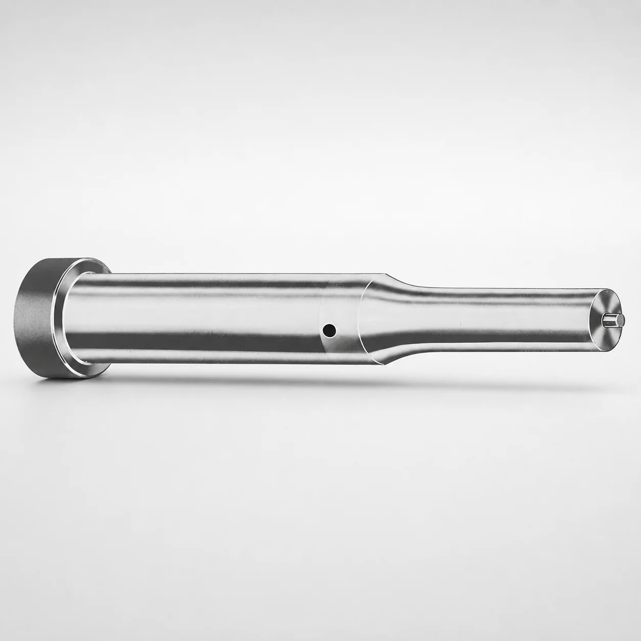
Inch Ejector Punches - XNT DayTiN® Coating
Inch ejector punches (XNT DayTiN® coating, DAYTON) are designed to provide stable punch action and improved wear behavior in die and mold applications. The thin coating system helps reduce friction and support long production runs.
- Tooling-grade ejector punch for dependable actuation in production molds
- XNT DayTiN® coating to enhance surface durability under repeated cycles
- Engineered for dimensional consistency to support proper alignment during ejection
- Suitable for die punching stations and progressive forming tooling
Specifications
750 configurations available
| Tip shape | D (Shank dia.) (in) | Jektole group | Standard [S] Point Length B & L (Length) (coded inch) | Alternate [B] Point Length B & L (Length) (coded inch) | Alternate [C] Point Length B & L (Length) (coded inch) | Alternate [D] Point Length B & L (Length) (coded inch) | Alternate [E] Point Length B & L (Length) (coded inch) | P Dimension (in) | W Dimension (in) | R Dimension (in) |
|---|---|---|---|---|---|---|---|---|---|---|
| H | 18(0.1875") | J2 | - | 150 ~ 400 | - | - | - | 0.062 ~ 0.1875 | 0.062 ~ 0.1875 | - |
| H | 18(0.1875") | J2 | 150 ~ 400 | - | - | - | - | 0.062 ~ 0.1875 | 0.062 ~ 0.1875 | - |
| H | 25(0.2500") | J3 | - | 150 ~ 400 | - | - | - | 0.08 ~ 0.25 | 0.08 ~ 0.0929 | - |
| H | 25(0.2500") | J3 | - | 150 ~ 400 | - | - | - | 0.08 ~ 0.25 | 0.093 ~ 0.25 | - |
| H | 25(0.2500") | J3 | 150 ~ 400 | - | - | - | - | 0.08 ~ 0.25 | 0.08 ~ 0.0929 | - |
| H | 25(0.2500") | J3 | 150 ~ 400 | - | - | - | - | 0.08 ~ 0.25 | 0.093 ~ 0.25 | - |
| H | 31(0.3125") | J4 | - | 150 ~ 600 | - | - | - | 0.115 ~ 0.3125 | 0.115 ~ 0.1249 | - |
| H | 31(0.3125") | J4 | - | 150 ~ 600 | - | - | - | 0.115 ~ 0.3125 | 0.125 ~ 0.3125 | - |
| H | 31(0.3125") | J4 | - | - | 175 ~ 600 | - | - | 0.115 ~ 0.3125 | 0.115 ~ 0.1249 | - |
| H | 31(0.3125") | J4 | - | - | 175 ~ 600 | - | - | 0.115 ~ 0.3125 | 0.125 ~ 0.3125 | - |
| H | 31(0.3125") | J4 | 150 ~ 600 | - | - | - | - | 0.115 ~ 0.3125 | 0.115 ~ 0.1249 | - |
| H | 31(0.3125") | J4 | 150 ~ 600 | - | - | - | - | 0.115 ~ 0.3125 | 0.125 ~ 0.3125 | - |
| H | 37(0.3750") | J6 | - | 175 ~ 625 | - | - | - | 0.158 ~ 0.375 | 0.158 ~ 0.1869 | - |
| H | 37(0.3750") | J6 | - | 175 ~ 625 | - | - | - | 0.158 ~ 0.375 | 0.187 ~ 0.375 | - |
| H | 37(0.3750") | J6 | - | - | 175 ~ 625 | - | - | 0.158 ~ 0.375 | 0.158 ~ 0.1869 | - |
| H | 37(0.3750") | J6 | - | - | 175 ~ 625 | - | - | 0.158 ~ 0.375 | 0.187 ~ 0.375 | - |
| H | 37(0.3750") | J6 | 175 ~ 625 | - | - | - | - | 0.158 ~ 0.375 | 0.158 ~ 0.1869 | - |
| H | 37(0.3750") | J6 | 175 ~ 625 | - | - | - | - | 0.158 ~ 0.375 | 0.187 ~ 0.375 | - |
| H | 43(0.4375") | J6 | - | - | 200 ~ 625 | - | - | 0.158 ~ 0.4375 | 0.158 ~ 0.1869 | - |
| H | 43(0.4375") | J6 | - | - | 200 ~ 625 | - | - | 0.158 ~ 0.4375 | 0.187 ~ 0.4375 | - |
| H | 43(0.4375") | J6 | 200 ~ 625 | - | - | - | - | 0.158 ~ 0.4375 | 0.158 ~ 0.1869 | - |
| H | 43(0.4375") | J6 | 200 ~ 625 | - | - | - | - | 0.158 ~ 0.4375 | 0.187 ~ 0.4375 | - |
| H | 50(0.5000") | J6 | - | - | 200 ~ 625 | - | - | 0.158 ~ 0.5 | 0.158 ~ 0.1869 | - |
| H | 50(0.5000") | J6 | - | - | 200 ~ 625 | - | - | 0.158 ~ 0.5 | 0.187 ~ 0.5 | - |
| H | 50(0.5000") | J6 | 200 ~ 625 | - | - | - | - | 0.158 ~ 0.5 | 0.158 ~ 0.1869 | - |
| H | 50(0.5000") | J6 | 200 ~ 625 | - | - | - | - | 0.158 ~ 0.5 | 0.187 ~ 0.5 | - |
| H | 62(0.6250") | J9 | - | - | - | 225 ~ 625 | - | 0.235 ~ 0.625 | 0.25 ~ 0.625 | - |
| H | 62(0.6250") | J9 | - | - | - | 225 ~ 625 | - | 0.235 ~ 0.625 | 0.235 ~ 0.2499 | - |
| H | 62(0.6250") | J9 | 225 ~ 625 | - | - | - | - | 0.235 ~ 0.625 | 0.25 ~ 0.625 | - |
| H | 62(0.6250") | J9 | 225 ~ 625 | - | - | - | - | 0.235 ~ 0.625 | 0.235 ~ 0.2499 | - |
| H | 75(0.7500") | J9 | - | - | - | 225 ~ 625 | - | 0.235 ~ 0.75 | 0.235 ~ 0.3119 | - |
| H | 75(0.7500") | J9 | - | - | - | 225 ~ 625 | - | 0.235 ~ 0.75 | 0.312 ~ 0.75 | - |
| H | 75(0.7500") | J9 | 225 ~ 625 | - | - | - | - | 0.235 ~ 0.75 | 0.235 ~ 0.3119 | - |
| H | 75(0.7500") | J9 | 225 ~ 625 | - | - | - | - | 0.235 ~ 0.75 | 0.312 ~ 0.75 | - |
| H | 87(0.8750") | J9 | - | - | - | 225 ~ 650 | - | 0.235 ~ 0.875 | 0.235 ~ 0.3119 | - |
| H | 87(0.8750") | J9 | - | - | - | 225 ~ 650 | - | 0.235 ~ 0.875 | 0.312 ~ 0.875 | - |
| H | 87(0.8750") | J9 | - | - | - | - | 225 ~ 650 | 0.235 ~ 0.875 | 0.235 ~ 0.3119 | - |
| H | 87(0.8750") | J9 | - | - | - | - | 225 ~ 650 | 0.235 ~ 0.875 | 0.312 ~ 0.875 | - |
| H | 87(0.8750") | J9 | 225 ~ 650 | - | - | - | - | 0.235 ~ 0.875 | 0.235 ~ 0.3119 | - |
| H | 87(0.8750") | J9 | 225 ~ 650 | - | - | - | - | 0.235 ~ 0.875 | 0.312 ~ 0.875 | - |
| H | 100(1.0000") | J9 | - | - | - | - | 250 ~ 650 | 0.235 ~ 1 | 0.235 ~ 0.3119 | - |
| H | 100(1.0000") | J9 | - | - | - | - | 250 ~ 650 | 0.235 ~ 1 | 0.312 ~ 1 | - |
| H | 100(1.0000") | J9 | 250 ~ 650 | - | - | - | - | 0.235 ~ 1 | 0.235 ~ 0.3119 | - |
| H | 100(1.0000") | J9 | 250 ~ 650 | - | - | - | - | 0.235 ~ 1 | 0.312 ~ 1 | - |
| H | 125(1.2500") | J12 | - | - | - | - | 250 ~ 700 | 0.281 ~ 1.25 | 0.281 ~ 0.3119 | - |
| H | 125(1.2500") | J12 | - | - | - | - | 250 ~ 700 | 0.281 ~ 1.25 | 0.312 ~ 1.25 | - |
| H | 125(1.2500") | J12 | 250 ~ 700 | - | - | - | - | 0.281 ~ 1.25 | 0.281 ~ 0.3119 | - |
| H | 125(1.2500") | J12 | 250 ��� 700 | - | - | - | - | 0.281 ~ 1.25 | 0.312 ~ 1.25 | - |
| H | 150(1.5000") | J12 | - | - | - | - | 250 ~ 700 | 0.281 ~ 1.5 | 0.281 ~ 0.3119 | - |
| H | 150(1.5000") | J12 | - | - | - | - | 250 ~ 700 | 0.281 ~ 1.5 | 0.312 ~ 1.5 | - |
Product Guide
Application Scenarios+
These inch ejector punches are used inside injection mold tooling to drive part ejection with stable stroke behavior and predictable return. The XNT DayTiN® coated surface is suited for applications where repeated sliding contact can accelerate wear, helping maintain consistent punch performance over long production runs.
- For automotive connector and housing molds, the high-cycle ejection action benefits from the low-friction coating, supporting reliable release without premature surface degradation.
- In consumer electronics enclosure tooling, dimensional consistency in the punch shank and tip geometry supports proper alignment during ejection, reducing the risk of cocking and uneven part release.
- In die punching and progressive forming stations, the range of tip shapes and standardized point lengths supports tooling designers who need robust actuation across varying stock thickness and forming layouts.
Material & Process Details+
Specification data provided for this series focuses on geometry and the XNT DayTiN® coating, not on an explicit steel grade or heat-treatment cycle. Therefore, the key performance-related material factors here are the coating’s wear-resistance contribution and its role in controlling friction at the punch-work interface.
- XNT DayTiN® coating: engineered as a thin coating system to improve surface durability under repeated ejection cycles, supporting consistent sliding behavior.
- Hardness / wear vs. toughness trade-off: coated punches typically prioritize wear resistance at the surface; designers should account for the balance between a harder surface and the underlying substrate toughness (not specified in the provided data).
- Multiple material options: not listed for this product; coating variant is the differentiator in the available specifications.
Sizing & Selection Guide+
Select an ejector punch size by matching the required shank diameter (D), tip shape, and overall point length (B & L) to the core/cavity ejection layout. This series provides D = 18 ~ 250 in and coded point length ranges including S = 150 ~ 250, with alternate B and C/D/E coding options extending up to 650 and beyond, depending on the specific length code.
- Choose the tip shape (H, J, K, L, N, O, R, V, X, Y, Z) that matches the part underside geometry for stable contact during ejection.
- Verify the P dimension (0.05 ~ 1.625 in) and W dimension (0.062 ~ 0.5 in) against the clearance and penetration constraints of the ejector bore and relief features.
- Confirm the R dimension (0.007 ~ 0.007 in) to ensure the required edge radius is compatible with the part surface to minimize marks.
If you work with ejector guide systems, ensure press-fit or clearance recommendations in your ejector plate/bushing design are satisfied; the provided data gives size ranges, while specific tolerance/fit values are not included here.
Frequently Asked Questions
Which tip shapes (H, J, K, L, N, O, R, V, X, Y, Z) should I select for stable ejection contact?+
Use the required tip geometry based on the part underside feature to ensure consistent contact during the ejection stroke. This series supports multiple tip shapes: H, J, K, L, N, O, R, V, X, Y, Z, so you can align the punch’s contact profile with your release area.
After selecting the tip shape, verify that the selected B & L point length code and P / W / R dimensions provide adequate clearance in the ejector layout.
What are the available shank diameter and point-length ranges for these inch ejector punches?+
The shank diameter range is D (shank dia.) = 18 ~ 250 in. Point length codes support S = 150 ~ 250, with alternate ranges such as B = 150 ~ 400, 150 ~ 600, or 175 ~ 625, and other coded options up to 650 depending on the lettered variant.
Confirm the exact length code your press-ready tooling layout requires by matching the cavity/core ejection depth and clearance envelope.
How does the XNT DayTiN® coating affect wear for high-cycle ejection in injection molds?+
The XNT DayTiN® coating is specified as a thin coating system intended to enhance surface durability under repeated cycles. In mold ejection applications, this helps reduce friction and supports long production runs by improving wear behavior at the punch contact surfaces.
Because the provided data does not list a specific steel grade or HRC, wear performance should be validated against your operating conditions (stroke frequency, load, and part material abrasiveness).
How do I choose the correct P, W, and R dimensions to avoid interference with the ejector plate or part surface?+
This series specifies size ranges for P = 0.05 ~ 1.625 in, W = 0.062 ~ 0.5 in, and a constant R dimension = 0.007 ~ 0.007 in. Use these values to check clearance in the ejector bore, relief pockets, and any guide hardware.
For part-surface protection, verify that the edge radius (R) is compatible with your release surface requirements to reduce cosmetic marking risk.
Can these punches be used in progressive forming die stations as well as injection tooling?+
Yes—tooling guidance in the provided description indicates suitability for die punching stations and progressive forming tooling. Select the tip shape and coded B & L point length that match your station’s contact geometry and working clearance needs.
Then confirm the D shank diameter fits the press layout and that the P / W / R features meet the required envelope.
Related Products






Need Custom Specifications?
Our engineering team can help with custom configurations, material selection, and volume pricing.