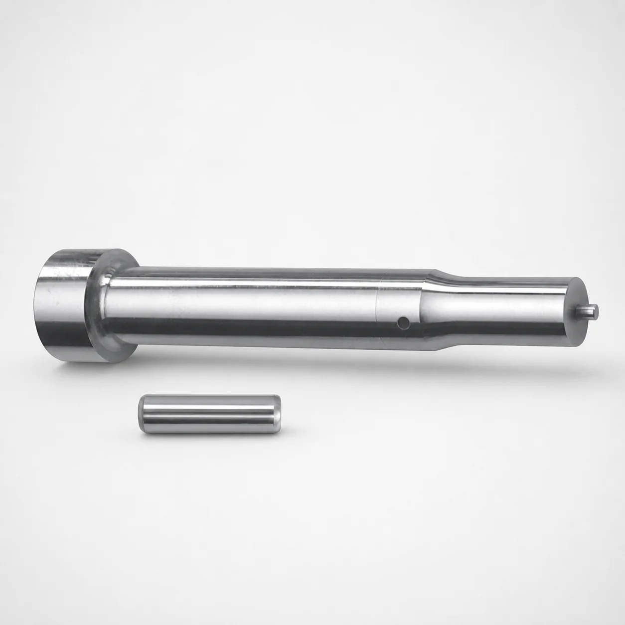
Metric Center Dowel Punches for Heavy Load with XVP Coating
Metric Center Dowel Punches for Heavy Load (XVP coating) are designed for reliable dowel positioning in heavy-duty mold assemblies, improving setup stability and guiding punch/locator alignment. Built for repeatable performance in production tooling.
- Heavy-load center dowel punch geometry for stable locating and alignment
- XVP coating supports wear resistance and consistent punch operation
- Available tip forms (X/R/K/O/H/L/J/N/V/Y/Z) to match different locating needs
- Metric compatibility for dowel-hole applications in stamping and molding equipment
Specifications
112 configurations available
| Tip shape | D (Shank diameter) (mm) | Jektole group | L1 (Point Length) (mm) | L (Length) (mm) | P Dimension (mm) | W Dimension (mm) | R Dimension (mm) |
|---|---|---|---|---|---|---|---|
| H | 10 | J6M | 13 ~ 19 | 80 ~ 130 | 4 ~ 4.99 | 4 ~ 4.99 | - |
| H | 10 | J6M | 13 ~ 19 | 80 ~ 130 | 4 ~ 4.99 | 5 ~ 10 | - |
| H | 10 | J6M | 13 ~ 19 | 80 ~ 130 | 5 ~ 10 | 4 ~ 4.99 | - |
| H | 10 | J6M | 13 ~ 19 | 80 ~ 130 | 5 ~ 10 | 5 ~ 10 | - |
| H | 13 | J6M | 13 ~ 19 | 80 ~ 130 | 4 ~ 5.99 | 4 ~ 5.99 | - |
| H | 13 | J6M | 13 ~ 19 | 80 ~ 130 | 4 ~ 5.99 | 6 ~ 13 | - |
| H | 13 | J6M | 13 ~ 19 | 80 ~ 130 | 6 ~ 13 | 4 ~ 5.99 | - |
| H | 13 | J6M | 13 ~ 19 | 80 ~ 130 | 6 ~ 13 | 6 ~ 13 | - |
| H | 16 | J9M | 19 ~ 25 | 80 ~ 130 | 6 ~ 16 | 6 ~ 16 | - |
| H | 20 | J9M | 19 ~ 25 | 80 ~ 130 | 6 ~ 20 | 6 ~ 20 | - |
| H | 25 | J9M | 19 ~ 25 | 80 ~ 130 | 6 ~ 25 | 6 ~ 25 | - |
| J | 10 | J6M | 13 ~ 19 | 80 ~ 130 | 4 ~ 4.99 | 4 ~ 4.99 | - |
| J | 10 | J6M | 13 ~ 19 | 80 ~ 130 | 4 ~ 4.99 | 5 ~ 10 | - |
| J | 10 | J6M | 13 ~ 19 | 80 ~ 130 | 5 ~ 10 | 4 ~ 4.99 | - |
| J | 10 | J6M | 13 ~ 19 | 80 ~ 130 | 5 ~ 10 | 5 ~ 10 | - |
| J | 13 | J6M | 13 ~ 19 | 80 ~ 130 | 4 ~ 5.99 | 4 ~ 5.99 | - |
| J | 13 | J6M | 13 ~ 19 | 80 ~ 130 | 4 ~ 5.99 | 6 ~ 13 | - |
| J | 13 | J6M | 13 ~ 19 | 80 ~ 130 | 6 ~ 13 | 4 ~ 5.99 | - |
| J | 13 | J6M | 13 ~ 19 | 80 ~ 130 | 6 ~ 13 | 6 ~ 13 | - |
| J | 16 | J9M | 19 ~ 25 | 80 ~ 130 | 6 ~ 16 | 6 ~ 16 | - |
| J | 20 | J9M | 19 ~ 25 | 80 ~ 130 | 6 ~ 20 | 6 ~ 20 | - |
| J | 25 | J9M | 19 ~ 25 | 80 ~ 130 | 6 ~ 25 | 6 ~ 25 | - |
| K | 10 | J6M | 13 ~ 19 | 80 ~ 130 | 4 ~ 4.99 | 4 ~ 4.99 | 0.2 ~ 5 |
| K | 10 | J6M | 13 ~ 19 | 80 ~ 130 | 4 ~ 4.99 | 5 ~ 10 | 0.2 ~ 5 |
| K | 10 | J6M | 13 ~ 19 | 80 ~ 130 | 5 ~ 10 | 4 ~ 4.99 | 0.2 ~ 5 |
| K | 10 | J6M | 13 ~ 19 | 80 ~ 130 | 5 ~ 10 | 5 ~ 10 | 0.2 ~ 5 |
| K | 13 | J6M | 13 ~ 19 | 80 ~ 130 | 4 ~ 5.99 | 4 ~ 5.99 | 0.2 ~ 6.5 |
| K | 13 | J6M | 13 ~ 19 | 80 ~ 130 | 4 ~ 5.99 | 6 ~ 13 | 0.2 ~ 6.5 |
| K | 13 | J6M | 13 ~ 19 | 80 ~ 130 | 6 ~ 13 | 4 ~ 5.99 | 0.2 ~ 6.5 |
| K | 13 | J6M | 13 ~ 19 | 80 ~ 130 | 6 ~ 13 | 6 ~ 13 | 0.2 ~ 6.5 |
| K | 16 | J9M | 19 ~ 25 | 80 ~ 130 | 6 ~ 16 | 6 ~ 16 | 0.2 ~ 8 |
| K | 20 | J9M | 19 ~ 25 | 80 ~ 130 | 6 ~ 20 | 6 ~ 20 | 0.2 ~ 10 |
| K | 25 | J9M | 19 ~ 25 | 80 ~ 130 | 6 ~ 25 | 6 ~ 25 | 0.2 ~ 12.5 |
| L | 10 | J6M | 13 ~ 19 | 80 ~ 130 | 4 ~ 4.99 | 4 ~ 4.99 | - |
| L | 10 | J6M | 13 ~ 19 | 80 ~ 130 | 4 ~ 4.99 | 5 ~ 10 | - |
| L | 10 | J6M | 13 ~ 19 | 80 ~ 130 | 5 ~ 10 | 4 ~ 4.99 | - |
| L | 10 | J6M | 13 ~ 19 | 80 ~ 130 | 5 ~ 10 | 5 ~ 10 | - |
| L | 13 | J6M | 13 ~ 19 | 80 ~ 130 | 4 ~ 5.99 | 4 ~ 5.99 | - |
| L | 13 | J6M | 13 ~ 19 | 80 ~ 130 | 4 ~ 5.99 | 6 ~ 13 | - |
| L | 13 | J6M | 13 ~ 19 | 80 ~ 130 | 6 ~ 13 | 4 ~ 5.99 | - |
| L | 13 | J6M | 13 ~ 19 | 80 ~ 130 | 6 ~ 13 | 6 ~ 13 | - |
| L | 16 | J9M | 19 ~ 25 | 80 ~ 130 | 6 ~ 16 | 6 ~ 16 | - |
| L | 20 | J9M | 19 ~ 25 | 80 ~ 130 | 6 ~ 20 | 6 ~ 20 | - |
| L | 25 | J9M | 19 ~ 25 | 80 ~ 130 | 6 ~ 25 | 6 ~ 25 | - |
| N | 10 | J6M | 13 ~ 19 | 80 ~ 130 | - | 4 ~ 4.99 | - |
| N | 10 | J6M | 13 ~ 19 | 80 ~ 130 | - | 5 ~ 10 | - |
| N | 13 | J6M | 13 ~ 19 | 80 ~ 130 | - | 4 ~ 5.99 | - |
| N | 13 | J6M | 13 ~ 19 | 80 ~ 130 | - | 6 ~ 13 | - |
| N | 16 | J9M | 19 ~ 25 | 80 ~ 130 | - | 6 ~ 16 | - |
| N | 20 | J9M | 19 ~ 25 | 80 ~ 130 | - | 6 ~ 20 | - |
Product Guide
Application Scenarios+
Center dowel punches with XVP coating are used to establish repeatable locator alignment in heavy-duty injection mold and stamping tooling. They are commonly installed in shut-off and tie-bar guided mold assemblies to ensure consistent punch-to-block positioning during press cycles.
- Automotive connector and bracket molds: When alignment stability directly impacts gate/insert positioning, the heavy-load geometry helps maintain locating accuracy under vibration and repeated clamping.
- Medical device housings with tight part-to-part registration: Use these center locators to stabilize mold half alignment, supporting consistent cavity location for thin-wall or fine-feature components.
- Industrial housings and appliance casings: The XVP coating is selected to improve wear resistance at the locating interface, helping maintain smooth operation across long service intervals.
Choose the appropriate metric shank diameter and tip form from the available options to match your dowel-hole geometry and ensure reliable seating within the mold assembly.
Material & Process Details+
The provided product data specifies an XVP coating for improved wear behavior at the dowel/punch locating surfaces. While the steel grade and hardness (HRC) are not specified in the input, the engineering intent is clear: the coated locating interface reduces abrasive wear and supports consistent punch operation over long production runs.
- Wear resistance: XVP coating is used to maintain dimensional stability at the locating point and minimize rounding or surface damage.
- Toughness trade-off: For heavy-load locating, the system prioritizes durable contact performance; however, exact toughness vs. hardness balance depends on the underlying steel grade, which is not provided.
- Heat treatment state: No heat treatment details (e.g., quenched & tempered, nitrided) were included in the provided specifications.
If you need confirmation of steel grade equivalence and target hardness for your application, share your preferred operating load and cycle life expectations so the correct material/condition can be verified.
Sizing & Selection Guide+
Select dimensions to match the mating dowel-hole and locator features in the mold base to ensure the punch seats correctly and maintains alignment.
- Choose shank diameter (D): Available D values are 10, 13, 16, 20, 25 mm. Match this to the corresponding hole diameter design on the mold block/plate.
- Select tip/probe form: Tip shape options include H, J, K, L, N, O, R, V, X, Y, Z. Use the form that best suits your locating engagement length and lead-in geometry.
- Set point length (L1): L1 ranges are 13–19 mm and 19–25 mm. Pick based on required engagement depth during mold clamping.
- Confirm overall length (L): L is fixed at 80–130 mm. Ensure clearance for installation and that the working tip can reach the locator surface without interference.
Pay attention to P (4–18 mm), W (4–6 mm), and R (0.2–5 / 0.2–6.5 / 0.2–8 / 0.2–10 / 0.2–12.5 mm) to align with your dowel-hole lead-in radii and tolerance/fit strategy. When dowel-hole tolerances are tight, ensure the selected tip form and shank diameter correspond to the intended clearance or press-fit condition used in your tooling design.
Frequently Asked Questions
Which tip shapes (H/J/K/L/N/O/R/V/X/Y/Z) should I choose for stable centering in heavy mold assemblies?+
The available tip shapes are H, J, K, L, N, O, R, V, X, Y, Z, and the best choice depends on your mold half lead-in and engagement geometry. If your assembly requires controlled centering during the final clamp position, select a tip form that provides the intended lead-in behavior for your dowel-hole design. Confirm the required engagement depth using L1 (13–19 mm or 19–25 mm).
What shank diameter range is offered, and how do I match it to my dowel-hole diameter?+
This series provides metric shank diameters D = 10, 13, 16, 20, 25 mm. Match the selected D to the corresponding dowel-hole diameter in your mold base or locating plate. If your design uses tight location tolerances, verify the mating feature diameter and the intended clearance/fit before finalizing.
How do I select point length L1 for the required engagement depth during clamping?+
Point length L1 is offered in two ranges: 13–19 mm and 19–25 mm. Choose the range that allows sufficient tip contact when the mold halves close, while maintaining clearance to avoid interference. The proper selection is typically validated against your clamp stroke, stop geometry, and dowel-hole depth.
Is the overall length L fixed, and what range should I check for installation clearance?+
The overall length L is specified as 80–130 mm. Treat this range as your allowable installation envelope and confirm that the punch can be mounted without contacting adjacent mold components. Also confirm that the working tip length (via L1) reaches the intended locating surface.
What does the XVP coating contribute for wear and long service life at the locating interface?+
The design includes an XVP coating intended to improve wear resistance and help maintain consistent locating/punch operation under heavy-load cycling. This is particularly relevant at the contact points where misalignment would quickly damage locating surfaces. For full material verification (steel grade and hardness), the input does not specify the base metal condition, so request confirmation if your process requires a specific HRC target.
Related Products

Metric Dowel Punches for Heavy Load with Single-Stepped Shank (M5)

Metric Center Dowel Punches for Heavy Load TiCN Coated

JIS Standard SKH51 Steel Ejector Punches for Heavy Load with Dowel Holes

SKH51 Steel TiCN Coating Ejector Punches for Heavy Load with Dowel Holes

RW Coated Dowel Punches for Heavy Load - Single-Stepped Shank

Center Dowel Ejector Punches for Heavy Load (RW Coating) - SKH51 Steel
Need Custom Specifications?
Our engineering team can help with custom configurations, material selection, and volume pricing.