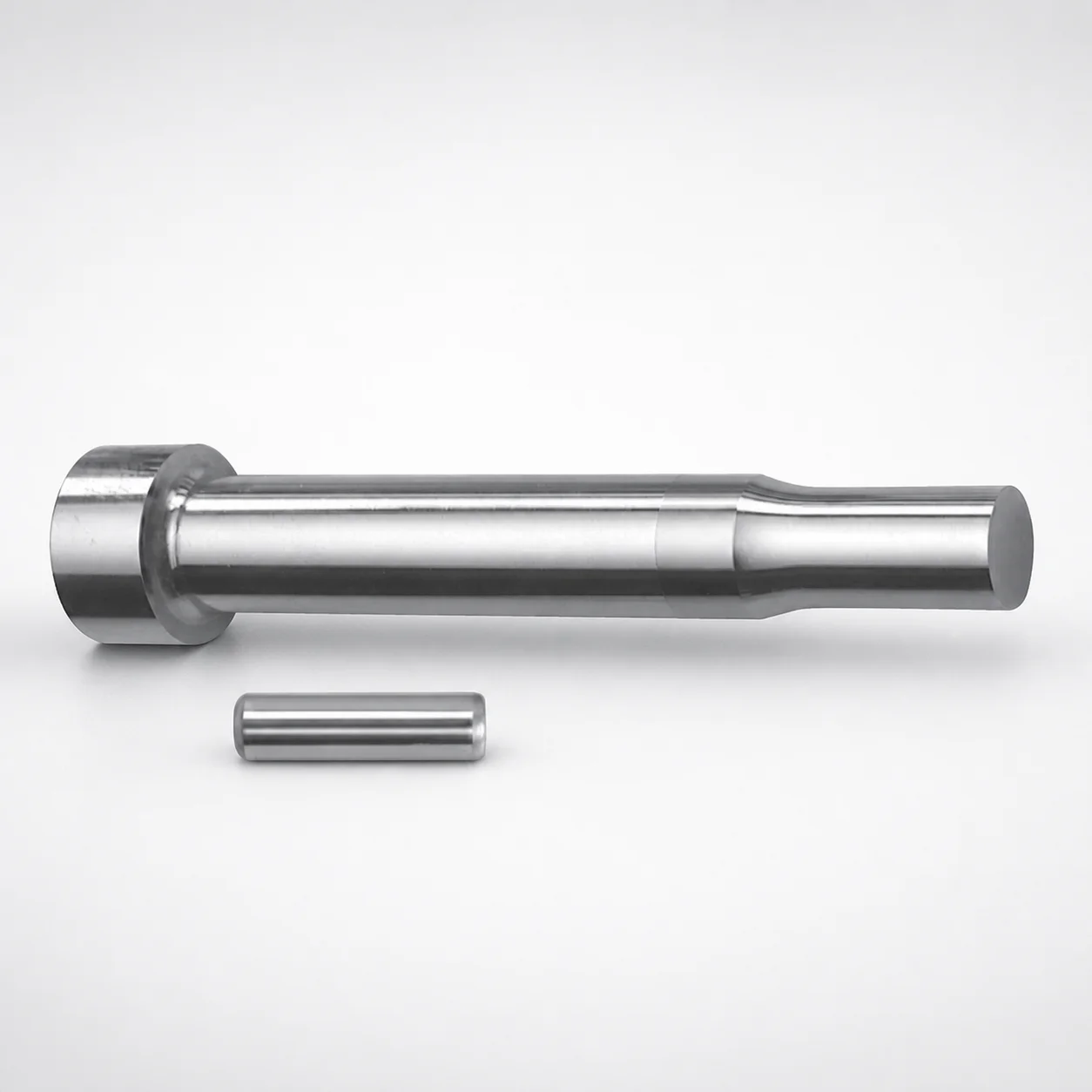
Metric Center Dowel Punches for Heavy Load
Metric Center Dowel Punches for Heavy Load from DAYTON are designed to locate and support heavy-duty tooling with a stable center point. The XNP coating helps improve surface durability in demanding press applications.
- Center dowel punch geometry for reliable die alignment and repeat positioning
- Surface enhanced by XNP coating to support long service intervals
- Multiple tip options for varied point engagement and forming conditions
- Suitable for heavy load work where dowel-hole guidance is critical
Specifications
164 configurations available
| Tip shape | D (Shank diameter) (mm) | L1 (Point Length) (mm) | L (Length) (mm) | P Dimension (mm) | W Dimension (mm) | R Dimension (mm) |
|---|---|---|---|---|---|---|
| H | 10 | 13 ~ 19 | 80 ~ 130 | 1.5 ~ 2.99 | 1.5 ~ 2.99 | - |
| H | 10 | 13 ~ 19 | 80 ~ 130 | 1.5 ~ 2.99 | 3 ~ 10 | - |
| H | 10 | 13 ~ 19 | 80 ~ 130 | 3 ~ 10 | 1.5 ~ 2.99 | - |
| H | 10 | 13 ~ 19 | 80 ~ 130 | 3 ~ 10 | 3 ~ 10 | - |
| H | 13 | 13 ~ 19 | 80 ~ 130 | 1.5 ~ 2.99 | 1.5 ~ 2.99 | - |
| H | 13 | 13 ~ 19 | 80 ~ 130 | 1.5 ~ 2.99 | 3 ~ 13 | - |
| H | 13 | 13 ~ 19 | 80 ~ 130 | 3 ~ 13 | 1.5 ~ 2.99 | - |
| H | 13 | 13 ~ 19 | 80 ~ 130 | 3 ~ 13 | 3 ~ 13 | - |
| H | 16 | 19 ~ 25 | 80 ~ 130 | 3 ~ 3.99 | 3 ~ 3.99 | - |
| H | 16 | 19 ~ 25 | 80 ~ 130 | 3 ~ 3.99 | 4 ~ 16 | - |
| H | 16 | 19 ~ 25 | 80 ~ 130 | 4 ~ 16 | 3 ~ 3.99 | - |
| H | 16 | 19 ~ 25 | 80 ~ 130 | 4 ~ 16 | 4 ~ 16 | - |
| H | 20 | 19 ~ 25 | 80 ~ 130 | 3 ~ 4.99 | 3 ~ 4.99 | - |
| H | 20 | 19 ~ 25 | 80 ~ 130 | 3 ~ 4.99 | 5 ~ 20 | - |
| H | 20 | 19 ~ 25 | 80 ~ 130 | 5 ~ 20 | 3 ~ 4.99 | - |
| H | 20 | 19 ~ 25 | 80 ~ 130 | 5 ~ 20 | 5 ~ 20 | - |
| H | 25 | 19 ~ 25 | 80 ~ 130 | 6 ~ 25 | 6 ~ 25 | - |
| J | 10 | 13 ~ 19 | 80 ~ 130 | 1.5 ~ 2.99 | 1.5 ~ 2.99 | - |
| J | 10 | 13 ~ 19 | 80 ~ 130 | 1.5 ~ 2.99 | 3 ~ 10 | - |
| J | 10 | 13 ~ 19 | 80 ~ 130 | 3 ~ 10 | 1.5 ~ 2.99 | - |
| J | 10 | 13 ~ 19 | 80 ~ 130 | 3 ~ 10 | 3 ~ 10 | - |
| J | 13 | 13 ~ 19 | 80 ~ 130 | 1.5 ~ 2.99 | 1.5 ~ 2.99 | - |
| J | 13 | 13 ~ 19 | 80 ~ 130 | 1.5 ~ 2.99 | 3 ~ 13 | - |
| J | 13 | 13 ~ 19 | 80 ~ 130 | 3 ~ 13 | 1.5 ~ 2.99 | - |
| J | 13 | 13 ~ 19 | 80 ~ 130 | 3 ~ 13 | 3 ~ 13 | - |
| J | 16 | 19 ~ 25 | 80 ~ 130 | 3 ~ 3.99 | 3 ~ 3.99 | - |
| J | 16 | 19 ~ 25 | 80 ~ 130 | 3 ~ 3.99 | 4 ~ 16 | - |
| J | 16 | 19 ~ 25 | 80 ~ 130 | 4 ~ 16 | 3 ~ 3.99 | - |
| J | 16 | 19 ~ 25 | 80 ~ 130 | 4 ~ 16 | 4 ~ 16 | - |
| J | 20 | 19 ~ 25 | 80 ~ 130 | 3 ~ 4.99 | 3 ~ 4.99 | - |
| J | 20 | 19 ~ 25 | 80 ~ 130 | 3 ~ 4.99 | 5 ~ 20 | - |
| J | 20 | 19 ~ 25 | 80 ~ 130 | 5 ~ 20 | 3 ~ 4.99 | - |
| J | 20 | 19 ~ 25 | 80 ~ 130 | 5 ~ 20 | 5 ~ 20 | - |
| J | 25 | 19 ~ 25 | 80 ~ 130 | 6 ~ 25 | 6 ~ 25 | - |
| K | 10 | 13 ~ 19 | 80 ~ 130 | 1.5 ~ 2.99 | 1.5 ~ 2.99 | 0.2 ~ 5 |
| K | 10 | 13 ~ 19 | 80 ~ 130 | 1.5 ~ 2.99 | 3 ~ 10 | 0.2 ~ 5 |
| K | 10 | 13 ~ 19 | 80 ~ 130 | 3 ~ 10 | 1.5 ~ 2.99 | 0.2 ~ 5 |
| K | 10 | 13 ~ 19 | 80 ~ 130 | 3 ~ 10 | 3 ~ 10 | 0.2 ~ 5 |
| K | 13 | 13 ~ 19 | 80 ~ 130 | 1.5 ~ 2.99 | 1.5 ~ 2.99 | 0.2 ~ 6.5 |
| K | 13 | 13 ~ 19 | 80 ~ 130 | 1.5 ~ 2.99 | 3 ~ 13 | 0.2 ~ 6.5 |
| K | 13 | 13 ~ 19 | 80 ~ 130 | 3 ~ 13 | 1.5 ~ 2.99 | 0.2 ~ 6.5 |
| K | 13 | 13 ~ 19 | 80 ~ 130 | 3 ~ 13 | 3 ~ 13 | 0.2 ~ 6.5 |
| K | 16 | 19 ~ 25 | 80 ~ 130 | 3 ~ 3.99 | 3 ~ 3.99 | 0.2 ~ 8 |
| K | 16 | 19 ~ 25 | 80 ~ 130 | 3 ~ 3.99 | 4 ~ 16 | 0.2 ~ 8 |
| K | 16 | 19 ~ 25 | 80 ~ 130 | 4 ~ 16 | 3 ~ 3.99 | 0.2 ~ 8 |
| K | 16 | 19 ~ 25 | 80 ~ 130 | 4 ~ 16 | 4 ~ 16 | 0.2 ~ 8 |
| K | 20 | 19 ~ 25 | 80 ~ 130 | 3 ~ 4.99 | 3 ~ 4.99 | 0.2 ~ 10 |
| K | 20 | 19 ~ 25 | 80 ~ 130 | 3 ~ 4.99 | 5 ~ 20 | 0.2 ~ 10 |
| K | 20 | 19 ~ 25 | 80 ~ 130 | 5 ~ 20 | 3 ~ 4.99 | 0.2 ~ 10 |
| K | 20 | 19 ~ 25 | 80 ~ 130 | 5 ~ 20 | 5 ~ 20 | 0.2 ~ 10 |
Product Guide
Application Scenarios+
This metric center dowel punch is used in injection and press tooling where repeat positioning and heavy-duty guidance are critical. Automotive connector and bracket molds often require tight die-to-core alignment across long production runs; the stable center-point geometry helps maintain consistent locating during opening/closing and reduces stack-up effects from repeated wear.
In appliance and power-tool enclosure tooling, the enhanced surface durability supports smoother sliding and more reliable hole engagement under higher loads. The XNP coating is suited to environments where abrasion and micro-scoring can otherwise shorten service intervals.
For progressive forming inserts and transfer mold tooling, select the appropriate tip shape (H, J, K, L, N, O, R, V, X, Y, Z) to match point engagement and forming conditions. The availability of multiple point geometries lets engineers optimize guidance without changing the fixed mounting length range used on the tooling.
- Use for die alignment and repeat positioning in heavy-load press/injection assemblies
- Choose tip shapes based on engagement needs and the forming profile
- Rely on XNP coating for improved surface durability under abrasive cycles
Material & Process Details+
The provided specifications describe geometry, dimensions, and the XNP coating, but they do not list the underlying steel grade or heat-treatment state (e.g., pre-hardened vs. quenched & tempered, nitrided). As a result, material-related properties such as HRC hardness, wear-resistance level, and toughness trade-offs cannot be stated from the input data.
What can be confirmed is that the XNP coating is intended to enhance surface durability for long service intervals, which typically improves resistance to abrasion and minor fretting at the locating interface. When selecting among variants, treat tip shape changes as contact-profile optimization, while the coating supports the durability requirement across repeated alignment cycles.
- Heat treatment: Not specified in the provided data
- Hardness (HRC): Not specified in the provided data
- Wear/toughness: Coating targets improved surface wear behavior; bulk toughness depends on base steel (not provided)
Sizing & Selection Guide+
Start by matching the locating geometry to your tooling interface. This center dowel punch uses a fixed length L = 80–130 mm, so choose the specific L value that fits your die/base thickness and provides adequate protrusion toward the mating dowel-hole pattern.
Select the shank diameter D (mm) from 10, 13, 16, 20, 25 to correspond to the reamed dowel-hole diameter and the guidance fit required in your press/injection assembly. Then choose point length L1 (mm) from 13–19 or 19–25 based on how deep the mating hole engagement needs to be for stable centering during closure.
For fine alignment behavior, configure the point geometry using P (1.5–18 mm), W (1.5–6 mm), and R from the offered ranges (0.2–5, 0.2–6.5, 0.2–8, 0.2–10, 0.2–12.5), and pick a tip shape (H, J, K, L, N, O, R, V, X, Y, Z) matched to your engagement and forming conditions.
- Fixed: L = 80–130 mm
- Variable: D, L1, tip shape, P, W, R
- Fit consideration: Ensure D matches the mating dowel-hole diameter and verify tolerances on both parts for consistent centering under load (tolerance values not provided in the data)
Frequently Asked Questions
Which tip shapes (H/J/K/L/N/O/R/V/X/Y/Z) should I consider for different die-hole engagement in heavy-load applications?+
Tip shapes are provided as H, J, K, L, N, O, R, V, X, Y, Z, and they are intended to tailor point engagement to process conditions. When selecting, consider how aggressively the point should enter the mating hole and how stable centering must be during closure. Since the underlying coating is the XNP coating, you can keep the durability strategy constant while changing the contact profile via tip shape.
How do I choose the correct shank diameter D for the mating dowel-hole size?+
The available D (shank diameter) values are 10, 13, 16, 20, 25 mm. Select the D that matches your reamed dowel-hole diameter requirement for guidance under heavy loads. Because tolerance values are not included in the provided data, confirm your hole reaming/tolerance plan separately to ensure consistent alignment and repeatability.
What is the recommended way to select point length L1 and fixed length L together?+
This product has a fixed length L = 80–130 mm, and a variable point length L1 = 13–19 mm or 19–25 mm. Choose L to fit your die/base thickness and mounting space, then choose L1 based on the required engagement depth inside the mating hole for stable centering. Ensure that increasing L1 does not cause interference within your tooling envelope.
What do the P, W, and R dimensions affect when configuring the center dowel punch?+
The configuration includes P from 1.5–18 mm, W from 1.5–6 mm, and R in multiple offered ranges: 0.2–5, 0.2–6.5, 0.2–8, 0.2–10, and 0.2–12.5. These parameters are used to define the point profile and curvature for engagement. Use them to tune contact geometry for your specific forming/closure conditions while keeping D and L/L1 aligned to your tooling interface.
Does the XNP coating change dimensional selection, or is it mainly for durability?+
The provided description associates the XNP coating with improved surface durability for long service intervals under demanding press applications. The dimensional selections you must match to the tooling interface remain D (10–25 mm), L (80–130 mm), and L1 (13–25 mm options), plus the configured P/W/R and tip shape. Since coating thickness is not provided, verify any coating-induced clearance requirements with your hole/profile tolerances.
Related Products

Metric Dowel Punches for Heavy Load with Single-Stepped Shank (M5)

Metric Center Dowel Punches for Heavy Load TiCN Coated

JIS Standard SKH51 Steel Ejector Punches for Heavy Load with Dowel Holes

SKH51 Steel TiCN Coating Ejector Punches for Heavy Load with Dowel Holes

RW Coated Dowel Punches for Heavy Load - Single-Stepped Shank

Center Dowel Ejector Punches for Heavy Load (RW Coating) - SKH51 Steel
Need Custom Specifications?
Our engineering team can help with custom configurations, material selection, and volume pricing.