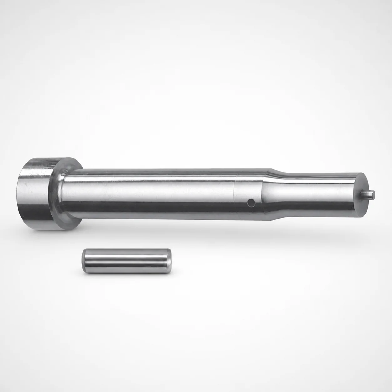
Metric XNM Coated Center Dowel Punches for Heavy Load
Center Dowel Punches for Heavy Load are designed for metric die assemblies where heavy-duty guiding and repeatable center positioning are required. The XNM coating helps extend service life under production wear conditions.
- Heavy-load center dowel punch geometry for stable dowel hole location during die operation
- XNM coating supports long wear life for high-cycle molding environments
- Multiple selectable tip shapes (X/R/K/O/H/L/J/N/V/Y/Z) to match tooling wear and contact needs
- Supports common die build lengths and shank diameters for flexible metric tooling integration
Specifications
112 configurations available
| Tip shape | D (Shank diameter) (mm) | Jektole group | L1 (Point Length) (mm) | L (Length) (mm) | P Dimension (mm) | W Dimension (mm) | R Dimension (mm) |
|---|---|---|---|---|---|---|---|
| H | 10 | J6M | 13 ~ 19 | 80 ~ 130 | 4 ~ 4.99 | 4 ~ 4.99 | - |
| H | 10 | J6M | 13 ~ 19 | 80 ~ 130 | 4 ~ 4.99 | 5 ~ 10 | - |
| H | 10 | J6M | 13 ~ 19 | 80 ~ 130 | 5 ~ 10 | 4 ~ 4.99 | - |
| H | 10 | J6M | 13 ~ 19 | 80 ~ 130 | 5 ~ 10 | 5 ~ 10 | - |
| H | 13 | J6M | 13 ~ 19 | 80 ~ 130 | 4 ~ 5.99 | 4 ~ 5.99 | - |
| H | 13 | J6M | 13 ~ 19 | 80 ~ 130 | 4 ~ 5.99 | 6 ~ 13 | - |
| H | 13 | J6M | 13 ~ 19 | 80 ~ 130 | 6 ~ 13 | 4 ~ 5.99 | - |
| H | 13 | J6M | 13 ~ 19 | 80 ~ 130 | 6 ~ 13 | 6 ~ 13 | - |
| H | 16 | J9M | 19 ~ 25 | 80 ~ 130 | 6 ~ 16 | 6 ~ 16 | - |
| H | 20 | J9M | 19 ~ 25 | 80 ~ 130 | 6 ~ 20 | 6 ~ 20 | - |
| H | 25 | J9M | 19 ~ 25 | 80 ~ 130 | 6 ~ 25 | 6 ~ 25 | - |
| J | 10 | J6M | 13 ~ 19 | 80 ~ 130 | 4 ~ 4.99 | 4 ~ 4.99 | - |
| J | 10 | J6M | 13 ~ 19 | 80 ~ 130 | 4 ~ 4.99 | 5 ~ 10 | - |
| J | 10 | J6M | 13 ~ 19 | 80 ~ 130 | 5 ~ 10 | 4 ~ 4.99 | - |
| J | 10 | J6M | 13 ~ 19 | 80 ~ 130 | 5 ~ 10 | 5 ~ 10 | - |
| J | 13 | J6M | 13 ~ 19 | 80 ~ 130 | 4 ~ 5.99 | 4 ~ 5.99 | - |
| J | 13 | J6M | 13 ~ 19 | 80 ~ 130 | 4 ~ 5.99 | 6 ~ 13 | - |
| J | 13 | J6M | 13 ~ 19 | 80 ~ 130 | 6 ~ 13 | 4 ~ 5.99 | - |
| J | 13 | J6M | 13 ~ 19 | 80 ~ 130 | 6 ~ 13 | 6 ~ 13 | - |
| J | 16 | J9M | 19 ~ 25 | 80 ~ 130 | 6 ~ 16 | 6 ~ 16 | - |
| J | 20 | J9M | 19 ~ 25 | 80 ~ 130 | 6 ~ 20 | 6 ~ 20 | - |
| J | 25 | J9M | 19 ~ 25 | 80 ~ 130 | 6 ~ 25 | 6 ~ 25 | - |
| K | 10 | J6M | 13 ~ 19 | 80 ~ 130 | 4 ~ 4.99 | 4 ~ 4.99 | 0.2 ~ 5 |
| K | 10 | J6M | 13 ~ 19 | 80 ~ 130 | 4 ~ 4.99 | 5 ~ 10 | 0.2 ~ 5 |
| K | 10 | J6M | 13 ~ 19 | 80 ~ 130 | 5 ~ 10 | 4 ~ 4.99 | 0.2 ~ 5 |
| K | 10 | J6M | 13 ~ 19 | 80 ~ 130 | 5 ~ 10 | 5 ~ 10 | 0.2 ~ 5 |
| K | 13 | J6M | 13 ~ 19 | 80 ~ 130 | 4 ~ 5.99 | 4 ~ 5.99 | 0.2 ~ 6.5 |
| K | 13 | J6M | 13 ~ 19 | 80 ~ 130 | 4 ~ 5.99 | 6 ~ 13 | 0.2 ~ 6.5 |
| K | 13 | J6M | 13 ~ 19 | 80 ~ 130 | 6 ~ 13 | 4 ~ 5.99 | 0.2 ~ 6.5 |
| K | 13 | J6M | 13 ~ 19 | 80 ~ 130 | 6 ~ 13 | 6 ~ 13 | 0.2 ~ 6.5 |
| K | 16 | J9M | 19 ~ 25 | 80 ~ 130 | 6 ~ 16 | 6 ~ 16 | 0.2 ~ 8 |
| K | 20 | J9M | 19 ~ 25 | 80 ~ 130 | 6 ~ 20 | 6 ~ 20 | 0.2 ~ 10 |
| K | 25 | J9M | 19 ~ 25 | 80 ~ 130 | 6 ~ 25 | 6 ~ 25 | 0.2 ~ 12.5 |
| L | 10 | J6M | 13 ~ 19 | 80 ~ 130 | 4 ~ 4.99 | 4 ~ 4.99 | - |
| L | 10 | J6M | 13 ~ 19 | 80 ~ 130 | 4 ~ 4.99 | 5 ~ 10 | - |
| L | 10 | J6M | 13 ~ 19 | 80 ~ 130 | 5 ~ 10 | 4 ~ 4.99 | - |
| L | 10 | J6M | 13 ~ 19 | 80 ~ 130 | 5 ~ 10 | 5 ~ 10 | - |
| L | 13 | J6M | 13 ~ 19 | 80 ~ 130 | 4 ~ 5.99 | 4 ~ 5.99 | - |
| L | 13 | J6M | 13 ~ 19 | 80 ~ 130 | 4 ~ 5.99 | 6 ~ 13 | - |
| L | 13 | J6M | 13 ~ 19 | 80 ~ 130 | 6 ~ 13 | 4 ~ 5.99 | - |
| L | 13 | J6M | 13 ~ 19 | 80 ~ 130 | 6 ~ 13 | 6 ~ 13 | - |
| L | 16 | J9M | 19 ~ 25 | 80 ~ 130 | 6 ~ 16 | 6 ~ 16 | - |
| L | 20 | J9M | 19 ~ 25 | 80 ~ 130 | 6 ~ 20 | 6 ~ 20 | - |
| L | 25 | J9M | 19 ~ 25 | 80 ~ 130 | 6 ~ 25 | 6 ~ 25 | - |
| N | 10 | J6M | 13 ~ 19 | 80 ~ 130 | - | 4 ~ 4.99 | - |
| N | 10 | J6M | 13 ~ 19 | 80 ~ 130 | - | 5 ~ 10 | - |
| N | 13 | J6M | 13 ~ 19 | 80 ~ 130 | - | 4 ~ 5.99 | - |
| N | 13 | J6M | 13 ~ 19 | 80 ~ 130 | - | 6 ~ 13 | - |
| N | 16 | J9M | 19 ~ 25 | 80 ~ 130 | - | 6 ~ 16 | - |
| N | 20 | J9M | 19 ~ 25 | 80 ~ 130 | - | 6 ~ 20 | - |
Product Guide
Application Scenarios+
This heavy-load metric center dowel punch is used in injection and compression die assemblies where accurate center positioning must be maintained through high cycling. In guiding applications, the punch supports repeatable dowel hole location during press open/close, reducing cumulative alignment drift when lots run continuously.
Common scenarios include:
- Automotive connector and terminal tooling: Use this variant with the XNM coating to improve wear resistance against frequent metal-to-metal contact in die lifters and guide stations.
- Thermoplastic housing and panel molds: The heavy-load center geometry helps stabilize center location for consistent cavity/core alignment, supporting uniform shut-off and reduced flash risk.
- High-cycle industrial parts: Select among the available tip shapes (H, J, K, L, N, O, R, V, X, Y, Z) to match contact/pointing needs for your die contact surface and wear profile.
Choose the appropriate shank diameter D (10–25 mm) and point length L1 (13–19 or 19–25 mm) to integrate reliably with your metric build dimensions.
Material & Process Details+
The provided metadata identifies a Dayton tool steel platform with an XNM coating intended for improved wear resistance in die assemblies. While a specific steel grade and measured hardness are not listed in the input data, the engineering intent is clear: the steel provides the core toughness for punch loading, and the coating increases surface durability.
How it performs in tooling:
- XNM coating: Designed to reduce abrasion and prolong service life under production wear conditions.
- Wear vs. toughness trade-off: Higher surface hardness/coating systems typically improve resistance to sliding and impact wear, while the underlying tool steel maintains toughness to survive repeated center-punch impacts.
- Heat treatment state: Not specified in the input; select the version offered by the manufacturer for your target duty cycle and contact wear profile.
If you need hardness (HRC) confirmation or a specific heat-treatment/grade (e.g., pre-hardened vs. quenched & tempered), request the spec sheet for series 250301835086.
Sizing & Selection Guide+
Select this metric center dowel punch by matching shank diameter D, point length L1, and the fixed overall length L (80–130 mm) to your die block thickness and guiding interface.
- Shank diameter D (mm): choose from 10, 13, 16, 20, or 25 to fit your die bushing/guide opening and ensure proper alignment of the punch axis.
- Point length L1 (mm): pick 13–19 mm or 19–25 mm based on required engagement depth into the mating contact zone for stable center location.
- Fixed length L (mm): use the available range 80–130 mm to suit your die assembly build height so the punch contacts correctly without overtravel.
For contact geometry, select a tip shape (H, J, K, L, N, O, R, V, X, Y, Z) to match pointing/contact needs. Dimensions P (4–18 mm), W (4–6 mm), and R (0.2–12.5 mm in multiple options) further define the contact profile; verify these against your mating die surfaces and desired wear behavior.
Tolerance/fit values are not provided in the input; confirm clearance and press-fit requirements with your die design standards and the manufacturer’s tolerance documentation for series 250301835086.
Frequently Asked Questions
Which shank diameter D options (mm) are available for series 250301835086 center dowel punches?+
How do I choose the correct point length L1 (13–19 vs 19–25 mm) for proper engagement?+
What tip shapes are offered, and when should a die designer select among H/J/K/L/N/O/R/V/X/Y/Z?+
What do the R and P dimension ranges mean for contact geometry in die assemblies?+
Does the XNM coating apply to all configurations of this heavy-load center dowel punch series?+
Related Products

Metric Dowel Punches for Heavy Load with Single-Stepped Shank (M5)

Metric Center Dowel Punches for Heavy Load TiCN Coated

JIS Standard SKH51 Steel Ejector Punches for Heavy Load with Dowel Holes

SKH51 Steel TiCN Coating Ejector Punches for Heavy Load with Dowel Holes

RW Coated Dowel Punches for Heavy Load - Single-Stepped Shank

Center Dowel Ejector Punches for Heavy Load (RW Coating) - SKH51 Steel
Need Custom Specifications?
Our engineering team can help with custom configurations, material selection, and volume pricing.