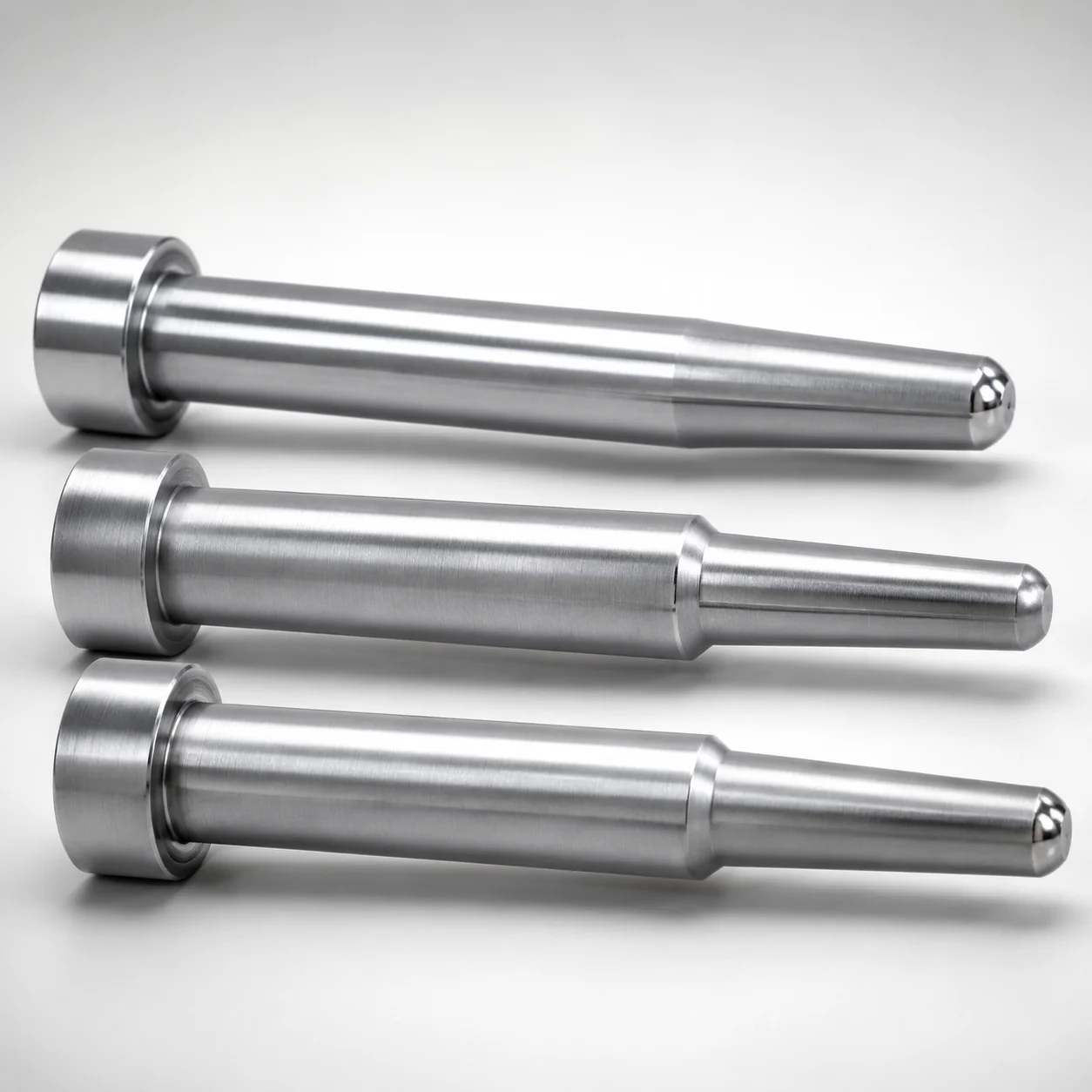
One-Step Core Pins Flat Sides
One-step core pins (hardened steel options) feature a single-step profile with flat sides to improve anti-rotation positioning and support consistent core ejection performance in production molds.
- One-step head geometry with flat-sided anti-rotation for stable location
- Available in SKH51/SKD61/NAK80/DH2F and other steels for wear resistance
- Supported for tight L-dimension and shaft tolerance requirements during assembly
- Designed for core and mold components needing precise alignment and repeatable ejection
Specifications
15075 configurations available
| Material | Shaft Diameter Tolerance | L Dimension Tolerance | Tip Gradient Tolerance | D/P (Shaft Diameter) (mm) | First Step Shape | Tip Shape | RE (R shape alteration・enlargement) (mm) | A (Step shape diameter) (mm) | C (Step type taper width) (mm) | CVC (Designation of C dimension in increments of 0.01mm) (mm) | F (Bearing bore length) (mm) | G (Tip C chamfering width) (mm) | K (Tip angle) (°) | L (L dimension) (mm) | Q (Tip R chamfering) (mm) | R (Step type R) (mm) | S (Tip tapered width) (mm) | V (Tip diameter) (mm) | VC (V dimension alteration, smaller than V min) (mm) | type |
|---|---|---|---|---|---|---|---|---|---|---|---|---|---|---|---|---|---|---|---|---|
| MAS1C | -0.01/-0.02 | +0.02/0 | ±0.015 | 1 | 1A | No processing | - | - | - | - | 10 ~ 99.5 | - | - | 12 ~ 100 | - | - | - | 0.5 ~ 0.99 | - | - |
| MAS1C | -0.01/-0.02 | +0.02/0 | ±0.015 | 1 | 1A | No processing | - | - | - | - | 10 ~ 99.5 | - | - | 12 ~ 100 | - | - | - | - | 0.4 ~ 0.49 | - |
| MAS1C | -0.01/-0.02 | +0.02/0 | ±0.015 | 1.5 | 1A | No processing | - | - | - | - | 10 ~ 99.5 | - | - | 12 ~ 100 | - | - | - | 0.5 ~ 1.49 | - | - |
| MAS1C | -0.01/-0.02 | +0.02/0 | ±0.015 | 1.5 | 1A | No processing | - | - | - | - | 10 ~ 99.5 | - | - | 12 ~ 100 | - | - | - | - | 0.4 ~ 0.49 | - |
| MAS1C | -0.01/-0.02 | +0.02/0 | ±0.015 | 2 | 1A | No processing | - | - | - | - | 10 ~ 99.5 | - | - | 12 ~ 100 | - | - | - | 0.5 ~ 1.99 | - | - |
| MAS1C | -0.01/-0.02 | +0.02/0 | ±0.015 | 2.5 | 1A | No processing | - | - | - | - | 10 ~ 99.5 | - | - | 12 ~ 100 | - | - | - | 0.5 ~ 2.49 | - | - |
| MAS1C | -0.01/-0.02 | 0/-0.1 | ±0.015 | 1 | 1A | B | - | - | - | - | 10 ~ 99.5 | - | - | 12 ~ 100 | - | - | - | 0.5 ~ 0.99 | - | - |
| MAS1C | -0.01/-0.02 | 0/-0.1 | ±0.015 | 1 | 1A | B | - | - | - | - | 10 ~ 99.5 | - | - | 12 ~ 100 | - | - | - | - | 0.4 ~ 0.49 | - |
| MAS1C | -0.01/-0.02 | 0/-0.1 | ±0.015 | 1.5 | 1A | B | - | - | - | - | 10 ~ 99.5 | - | - | 12 ~ 100 | - | - | - | 0.5 ~ 1.49 | - | - |
| MAS1C | -0.01/-0.02 | 0/-0.1 | ±0.015 | 1.5 | 1A | B | - | - | - | - | 10 ~ 99.5 | - | - | 12 ~ 100 | - | - | - | - | 0.4 ~ 0.49 | - |
| MAS1C | -0.01/-0.02 | 0/-0.1 | ±0.015 | 2 | 1A | B | - | - | - | - | 10 ~ 99.5 | - | - | 12 ~ 100 | - | - | - | 0.5 ~ 1.99 | - | - |
| MAS1C | -0.01/-0.02 | 0/-0.1 | ±0.015 | 2.5 | 1A | B | - | - | - | - | 10 ~ 99.5 | - | - | 12 ~ 100 | - | - | - | 0.5 ~ 2.49 | - | - |
| MAS1C | -0.01/-0.02 | +0.02/0 | ±0.015 | 1 | 1A | C | - | - | - | - | 10 ~ 99.5 | 0.3 ~ 0.4 | - | 12 ~ 100 | - | - | - | 0.5 ~ 0.99 | - | - |
| MAS1C | -0.01/-0.02 | +0.02/0 | ±0.015 | 1 | 1A | C | - | - | - | - | 10 ~ 99.5 | 0.3 ~ 0.4 | - | 12 ~ 100 | - | - | - | - | 0.4 ~ 0.49 | - |
| MAS1C | -0.01/-0.02 | +0.02/0 | ±0.015 | 1.5 | 1A | C | - | - | - | - | 10 ~ 99.5 | 0.5 ~ 0.7 | - | 12 ~ 100 | - | - | - | 0.5 ~ 1.49 | - | - |
| MAS1C | -0.01/-0.02 | +0.02/0 | ±0.015 | 1.5 | 1A | C | - | - | - | - | 10 ~ 99.5 | 0.5 ~ 0.7 | - | 12 ~ 100 | - | - | - | - | 0.4 ~ 0.49 | - |
| MAS1C | -0.01/-0.02 | +0.02/0 | ±0.015 | 2 | 1A | C | - | - | - | - | 10 ~ 99.5 | 0.5 ~ 0.9 | - | 12 ~ 100 | - | - | - | 0.5 ~ 1.99 | - | - |
| MAS1C | -0.01/-0.02 | +0.02/0 | ±0.015 | 2.5 | 1A | C | - | - | - | - | 10 ~ 99.5 | 0.5 ~ 1.2 | - | 12 ~ 100 | - | - | - | 0.5 ~ 2.49 | - | - |
| MAS1C | -0.01/-0.02 | 0/-0.1 | ±0.015 | 1 | 1A | G | - | - | - | - | 10 ~ 99.5 | - | 21 ~ 60 | 12 ~ 100 | - | - | - | 0.5 ~ 0.99 | - | - |
| MAS1C | -0.01/-0.02 | 0/-0.1 | ±0.015 | 1 | 1A | G | - | - | - | - | 10 ~ 99.5 | - | 21 ~ 60 | 12 ~ 100 | - | - | - | - | 0.4 ~ 0.49 | - |
| MAS1C | -0.01/-0.02 | 0/-0.1 | ±0.015 | 1.5 | 1A | G | - | - | - | - | 10 ~ 99.5 | - | 21 ~ 60 | 12 ~ 100 | - | - | - | 0.5 ~ 1.49 | - | - |
| MAS1C | -0.01/-0.02 | 0/-0.1 | ±0.015 | 1.5 | 1A | G | - | - | - | - | 10 ~ 99.5 | - | 21 ~ 60 | 12 ~ 100 | - | - | - | - | 0.4 ~ 0.49 | - |
| MAS1C | -0.01/-0.02 | 0/-0.1 | ±0.015 | 2 | 1A | G | - | - | - | - | 10 ~ 99.5 | - | 21 ~ 60 | 12 ~ 100 | - | - | - | 0.5 ~ 1.99 | - | - |
| MAS1C | -0.01/-0.02 | 0/-0.1 | ±0.015 | 2.5 | 1A | G | - | - | - | - | 10 ~ 99.5 | - | 21 ~ 60 | 12 ~ 100 | - | - | - | 0.5 ~ 2.49 | - | - |
| MAS1C | -0.01/-0.02 | +0.02/0 | ±0.015 | 1 | 1A | R | - | - | - | - | 10 ~ 99.5 | - | - | 12 ~ 100 | 0.2 ~ 0.4 | - | - | 0.5 ~ 0.99 | - | - |
| MAS1C | -0.01/-0.02 | +0.02/0 | ±0.015 | 1 | 1A | R | - | - | - | - | 10 ~ 99.5 | - | - | 12 ~ 100 | 0.2 ~ 0.4 | - | - | - | 0.4 ~ 0.49 | - |
| MAS1C | -0.01/-0.02 | +0.02/0 | ±0.015 | 1.5 | 1A | R | - | - | - | - | 10 ~ 99.5 | - | - | 12 ~ 100 | 0.2 ~ 0.7 | - | - | 0.5 ~ 1.49 | - | - |
| MAS1C | -0.01/-0.02 | +0.02/0 | ±0.015 | 1.5 | 1A | R | - | - | - | - | 10 ~ 99.5 | - | - | 12 ~ 100 | 0.2 ~ 0.7 | - | - | - | 0.4 ~ 0.49 | - |
| MAS1C | -0.01/-0.02 | +0.02/0 | ±0.015 | 2 | 1A | R | - | - | - | - | 10 ~ 99.5 | - | - | 12 ~ 100 | 0.2 ~ 0.9 | - | - | 0.5 ~ 1.99 | - | - |
| MAS1C | -0.01/-0.02 | +0.02/0 | ±0.015 | 2.5 | 1A | R | - | - | - | - | 10 ~ 99.5 | - | - | 12 ~ 100 | 0.2 ~ 1.2 | - | - | 0.5 ~ 2.49 | - | - |
| MAS1C | -0.01/-0.02 | +0.02/0 | ±0.015 | 1 | 1A | T | - | - | - | - | 10 ~ 99.5 | - | 10 ~ 45 | 12 ~ 100 | - | - | 0.1 ~ 15 | 0.5 ~ 0.99 | - | - |
| MAS1C | -0.01/-0.02 | +0.02/0 | ±0.015 | 1 | 1A | T | - | - | - | - | 10 ~ 99.5 | - | 10 ~ 45 | 12 ~ 100 | - | - | 0.1 ~ 15 | - | 0.4 ~ 0.49 | - |
| MAS1C | -0.01/-0.02 | +0.02/0 | ±0.015 | 1.5 | 1A | T | - | - | - | - | 10 ~ 99.5 | - | 10 ~ 45 | 12 ~ 100 | - | - | 0.1 ~ 20 | 0.5 ~ 1.49 | - | - |
| MAS1C | -0.01/-0.02 | +0.02/0 | ±0.015 | 1.5 | 1A | T | - | - | - | - | 10 ~ 99.5 | - | 10 ~ 45 | 12 ~ 100 | - | - | 0.1 ~ 20 | - | 0.4 ~ 0.49 | - |
| MAS1C | -0.01/-0.02 | +0.02/0 | ±0.015 | 2 | 1A | T | - | - | - | - | 10 ~ 99.5 | - | 10 ~ 45 | 12 ~ 100 | - | - | 0.1 ~ 25 | 0.5 ~ 1.99 | - | - |
| MAS1C | -0.01/-0.02 | +0.02/0 | ±0.015 | 2.5 | 1A | T | - | - | - | - | 10 ~ 99.5 | - | 10 ~ 45 | 12 ~ 100 | - | - | 0.1 ~ 30 | 0.5 ~ 2.49 | - | - |
| MAS1C | -0.01/-0.02 | +0.02/0 | ±0.015 | 1 | 1B | No processing | - | 0.4 ~ 0.99 | - | - | 10 ~ 99.5 | - | - | 12 ~ 100 | - | - | - | 0.5 ~ 0.99 | - | - |
| MAS1C | -0.01/-0.02 | +0.02/0 | ±0.015 | 1 | 1B | No processing | - | 0.4 ~ 0.99 | - | - | 10 ~ 99.5 | - | - | 12 ~ 100 | - | - | - | - | 0.4 ~ 0.49 | - |
| MAS1C | -0.01/-0.02 | +0.02/0 | ±0.015 | 1.5 | 1B | No processing | - | 0.4 ~ 1.49 | - | - | 10 ~ 99.3 | - | - | 12 ~ 100 | - | - | - | 0.5 ~ 1.49 | - | - |
| MAS1C | -0.01/-0.02 | +0.02/0 | ±0.015 | 1.5 | 1B | No processing | - | 0.4 ~ 1.49 | - | - | 10 ~ 99.3 | - | - | 12 ~ 100 | - | - | - | - | 0.4 ~ 0.49 | - |
| MAS1C | -0.01/-0.02 | +0.02/0 | ±0.015 | 2 | 1B | No processing | - | 0.5 ~ 1.99 | - | - | 10 ~ 99.3 | - | - | 12 ~ 100 | - | - | - | 0.5 ~ 1.99 | - | - |
| MAS1C | -0.01/-0.02 | +0.02/0 | ±0.015 | 2.5 | 1B | No processing | - | 0.5 ~ 2.49 | - | - | 10 ~ 99.3 | - | - | 12 ~ 100 | - | - | - | 0.5 ~ 2.49 | - | - |
| MAS1C | -0.01/-0.02 | 0/-0.1 | ±0.015 | 1 | 1B | B | - | 0.4 ~ 0.99 | - | - | 10 ~ 99.5 | - | - | 12 ~ 100 | - | - | - | 0.5 ~ 0.99 | - | - |
| MAS1C | -0.01/-0.02 | 0/-0.1 | ±0.015 | 1 | 1B | B | - | 0.4 ~ 0.99 | - | - | 10 ~ 99.5 | - | - | 12 ~ 100 | - | - | - | - | 0.4 ~ 0.49 | - |
| MAS1C | -0.01/-0.02 | 0/-0.1 | ±0.015 | 1.5 | 1B | B | - | 0.4 ~ 1.49 | - | - | 10 ~ 99.5 | - | - | 12 ~ 100 | - | - | - | 0.5 ~ 1.49 | - | - |
| MAS1C | -0.01/-0.02 | 0/-0.1 | ±0.015 | 1.5 | 1B | B | - | 0.4 ~ 1.49 | - | - | 10 ~ 99.5 | - | - | 12 ~ 100 | - | - | - | - | 0.4 ~ 0.49 | - |
| MAS1C | -0.01/-0.02 | 0/-0.1 | ±0.015 | 2 | 1B | B | - | 0.5 ~ 1.99 | - | - | 10 ~ 99.5 | - | - | 12 ~ 100 | - | - | - | 0.5 ~ 1.99 | - | - |
| MAS1C | -0.01/-0.02 | 0/-0.1 | ±0.015 | 2.5 | 1B | B | - | 0.5 ~ 2.49 | - | - | 10 ~ 99.5 | - | - | 12 ~ 100 | - | - | - | 0.5 ~ 2.49 | - | - |
| MAS1C | -0.01/-0.02 | +0.02/0 | ±0.015 | 1 | 1B | C | - | 0.4 ~ 0.99 | - | - | 10 ~ 99.5 | 0.3 ~ 0.4 | - | 12 ~ 100 | - | - | - | 0.5 ~ 0.99 | - | - |
| MAS1C | -0.01/-0.02 | +0.02/0 | ±0.015 | 1 | 1B | C | - | 0.4 ~ 0.99 | - | - | 10 ~ 99.5 | 0.3 ~ 0.4 | - | 12 ~ 100 | - | - | - | - | 0.4 ~ 0.49 | - |
Product Guide
Application Scenarios+
One-step core pins with flat sides are used in injection mold tooling where precise core location and repeatable ejection stroke are critical. The flat-sided anti-rotation head helps maintain angular stability during cycle start/stop, reducing wear at the bearing interface and helping ensure consistent core alignment.
In automotive and appliance connector molds, these pins support stepped core geometries that must eject housings or terminal components without drifting. The one-step profile with controlled L-dimension tolerance is suited to molds that require stable positioning under high production rate and frequent core loading.
For medical device housings and other tight-tolerance plastic parts, choosing a hardened steel option improves dimensional stability at elevated mold temperatures. Available shaft diameter and tight tolerance bands allow designers to match bearing length and step location to the core support system.
- Anti-rotation locating via flat sides for stable core engagement
- Repeatable ejection supported by L-dimension tolerance control
- Steel options for wear resistance in continuous production
Material & Process Details+
This core pin series is selectable across multiple steel grades depending on wear, toughness, and expected mold temperature. Options include SKD61 (commonly used as an H13-class hot-work tool steel), SKH51 (high-speed steel for improved wear resistance), NAK80 (pre-hardened, commonly selected for dimensional stability), DH2F (tool steel variant for wear resistance applications), and STAVAX ESR (ESR-refined tool steel for cleaner microstructure).
Exact hardness (HRC) and heat treatment state are not provided in the supplied data, but these grades are typically chosen to balance wear resistance vs. toughness. Higher-wear grades such as high-speed steels generally trade slightly lower toughness for increased abrasion resistance under sliding contact. For corrosive or cleanliness-sensitive processes, stainless SUS440C can be considered versus carbon/tool steels.
- Wear resistance: SKH51 / NAK80 / DH2F selections
- Balance for hot molding: SKD61 class steels
- Cleaner microstructure: STAVAX ESR
- Material alternatives: MAS1C, PROVA400, SUS440C (select by application requirements)
Sizing & Selection Guide+
Selection starts with the shaft diameter D/P (1 ~ 20 mm) and then the overall locating geometry defined by the L dimension (12 ~ 30 mm). To ensure stable anti-rotation seating, match the flat-sided head and stepped profile to the mold plate and core support bore system.
Use the tolerance bands to verify fit during assembly. The shaft diameter tolerance is available as -0.01/-0.02 or 0/-0.005, while the L-dimension tolerance is available as +0.02/0, 0/-0.1. Choose the tighter match for sliding/bearing setups where clearance and repeatability affect ejection alignment.
- Step geometry: select first step shape 1A–1E, plus step parameters such as A (0.4–4 mm) and C (0.1–4 mm or grouped ranges)
- Bearing length: confirm F (10 ~ 28 mm) to align with the core/mold interface length
- Tip features: choose tip shape (No processing, B/C/G/R/T) and gradient tolerance ±0.015/±0.01/±0.01
Finally, verify the tip alteration parameters (e.g., RE 0.5 ~ 2 mm) and the available tight tolerances on diameter and L for reliable locating without binding.
Frequently Asked Questions
Which shaft diameter tolerance option should I choose for one-step core pins with flat sides?+
For this series, the shaft diameter (D/P) tolerance can be specified as -0.01/-0.02 or 0/-0.005 for D/P values from 1 to 20 mm. Choose the 0/-0.005 band when you need tighter control toward maximum size for consistent locating. Choose -0.01/-0.02 when your bore system can accommodate slight undersize to avoid interference.
How do I match the L dimension tolerance to the core support and ejection alignment requirements?+
The L dimension is available over 12 to 30 mm with two tolerance sets: +0.02/0 or 0/-0.1. If your assembly stack-up is sensitive to excess length, prefer 0/-0.1 to reduce risk of over-length. If you need to guarantee a minimum engagement length for stable ejection timing, prefer +0.02/0.
What should I verify about the stepped tip geometry when selecting step shapes 1A–1E and tip shapes?+
Besides the first step shape (1A, 1B, 1C, 1D, 1E), the tip can be selected as No processing or B/C/G/R/T. Confirm compatibility with the mating core start/bearing feature using the specified step parameters such as A (0.4–4 mm), C (multiple ranges), and tip gradient tolerance (±0.015 / ±0.01 / ±0.01). This reduces the chance of mismatch that could impair alignment.
How do the available steel grades affect wear resistance and selection for production molds?+
Steel is configurable among MAS1C, SKD61, STAVAX ESR, DH2F, SKH51, NAK80, PROVA400, and SUS440C. For wear-prone, high-cycle tooling, designers often select harder/wear-resistant grades such as SKH51 or NAK80/DH2F. For hot-work applications where toughness and performance under molding heat are important, SKD61 class selection is commonly chosen. Confirm final suitability based on your mold temperature, duty cycle, and corrosion environment.
What parameters control the stepped interface and tip alteration for proper locating performance?+
The interface and tip alteration are controlled by parameters including F (10–28 mm) for bearing bore length, RE (0.5–2 mm) for R-shape alteration/enlargement, and chamfer/taper-related parameters like G (0.3–2 mm) and K (21–60° and other grouped ranges). Ensure these match the corresponding mold cavity/core features so the flat-sided pin locates without binding while maintaining stable anti-rotation during ejection.
Related Products
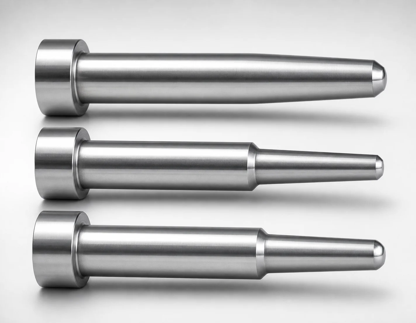
JIS Standard SKH51 Steel One-Step Core Pins - No Second Step
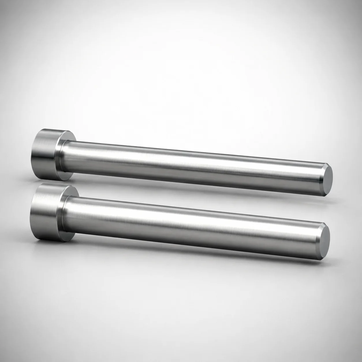
SKH51 Steel Precision Tip Short One-Step Core Pins
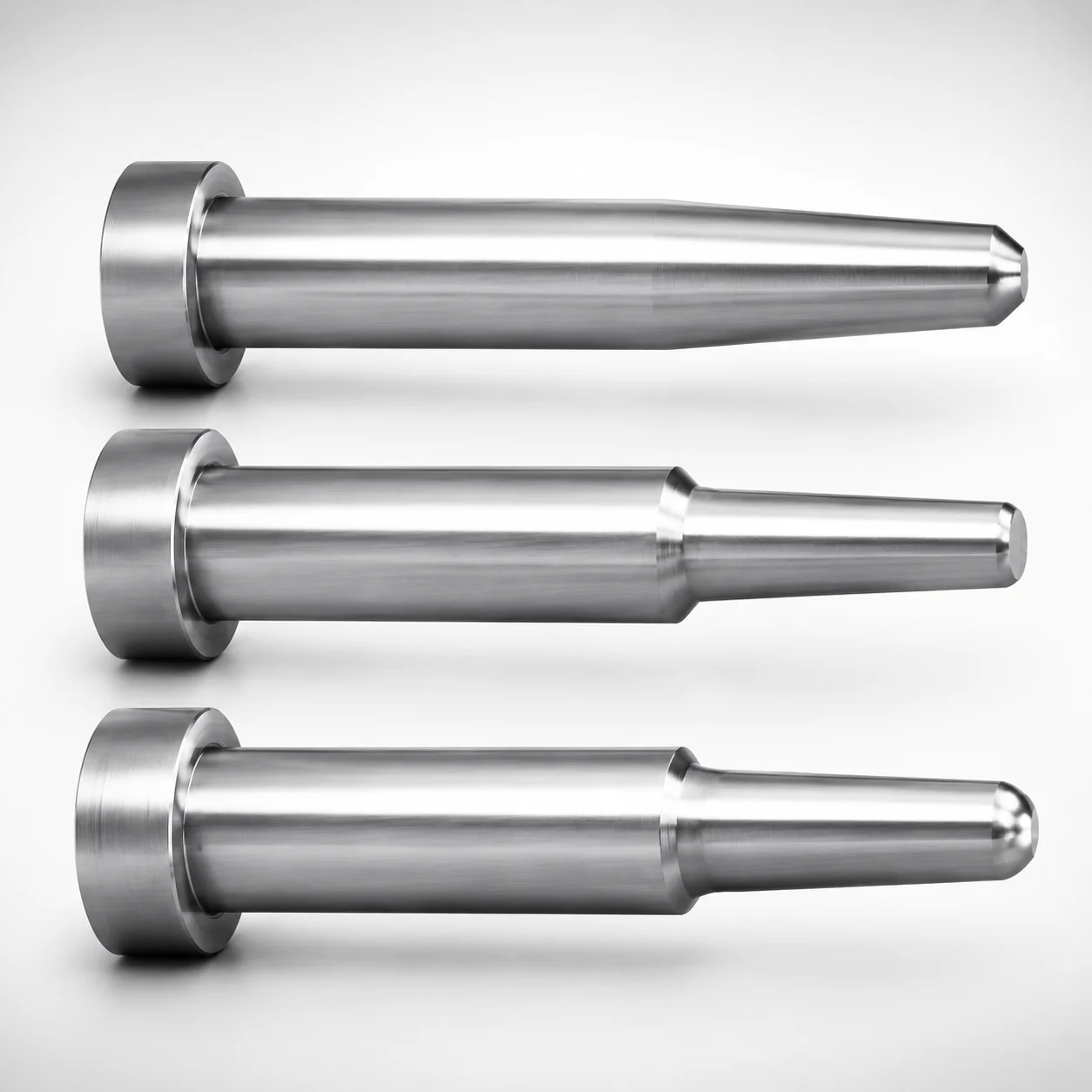
JIS Standard Precision One-Step Core Pins T4 Head
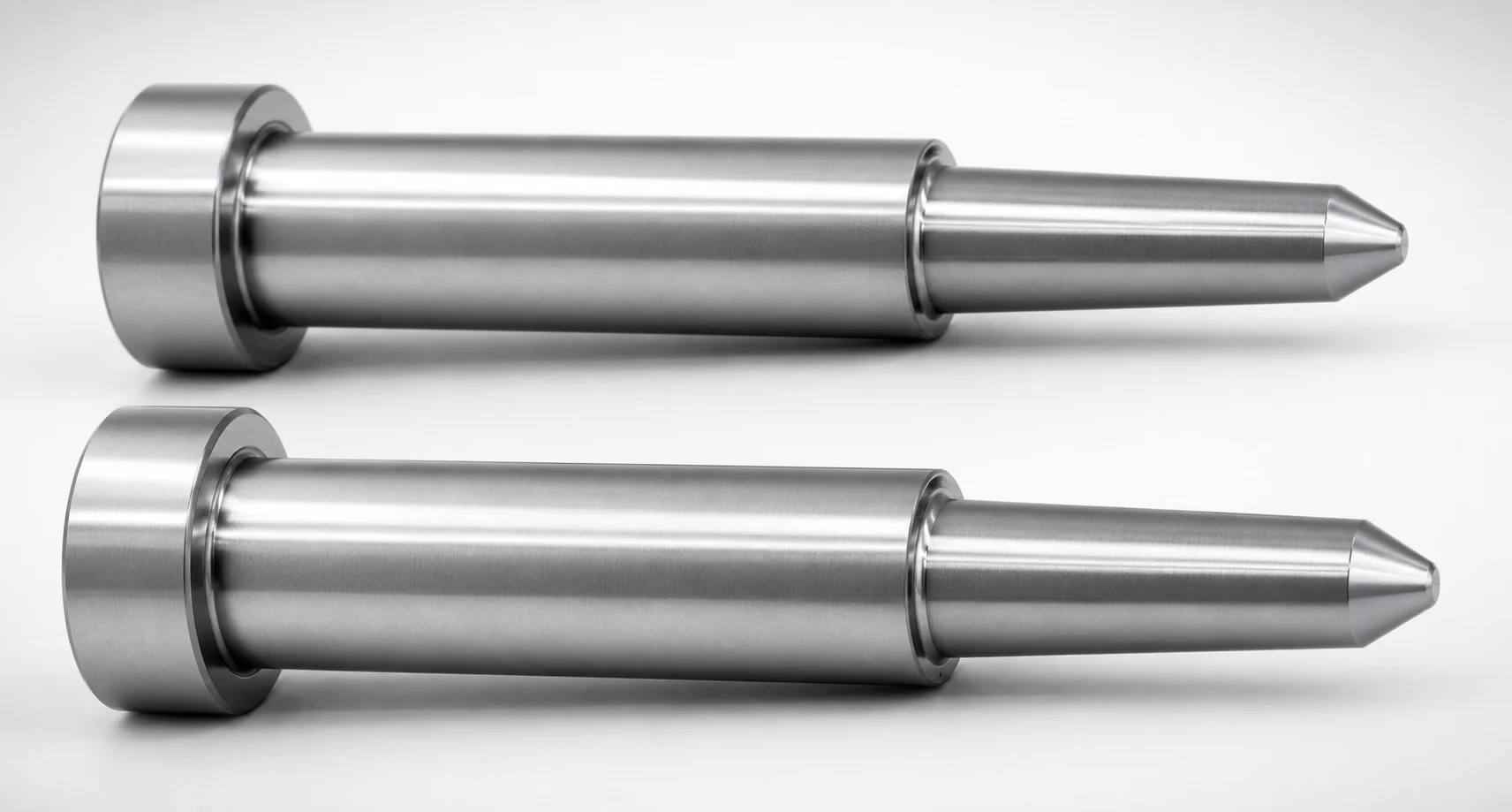
JIS Standard Precision One-Step Core Pins No Second Step
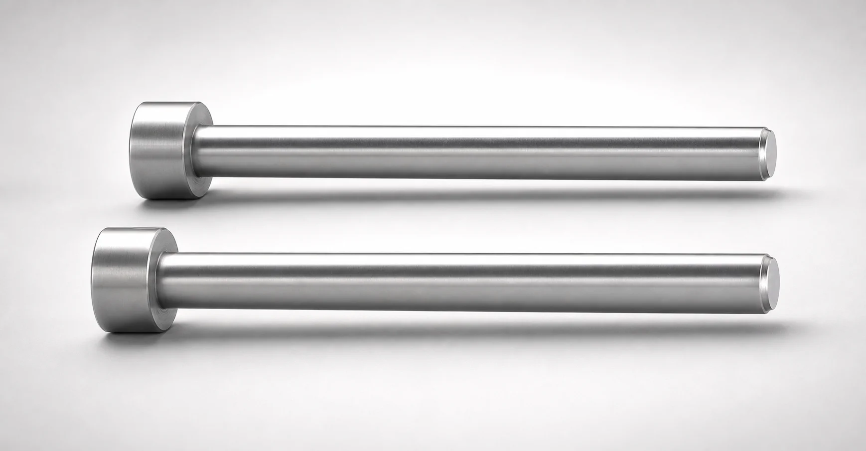
JIS Standard Precision Tip Short One-Step Core Pins
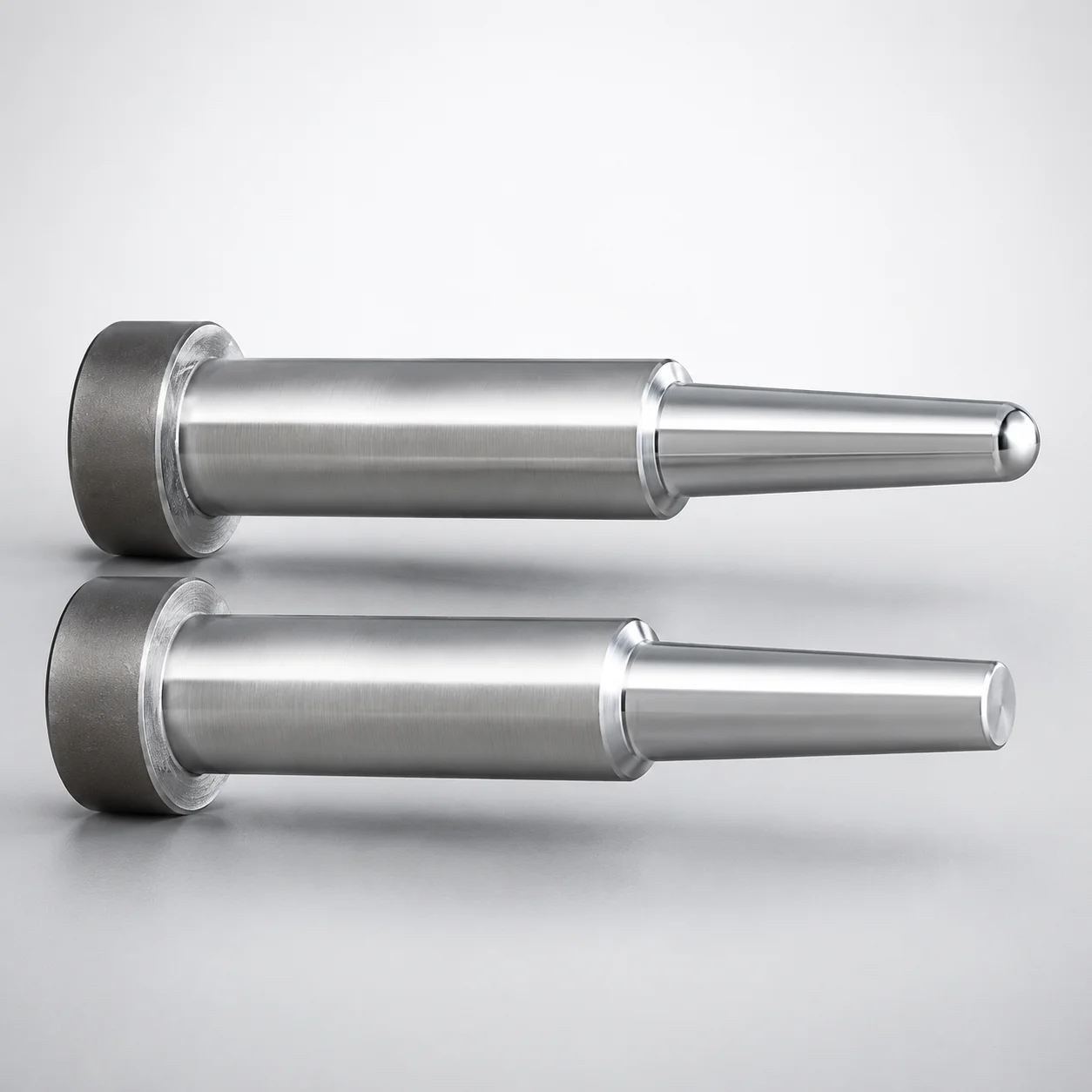
JIS Standard Steel One-Step Core Pins - Tip Lapped
Need Custom Specifications?
Our engineering team can help with custom configurations, material selection, and volume pricing.