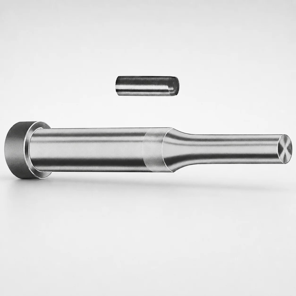
Metric Center Dowel Regular Punches
Metric Center Dowel Regular Punches (DAYTON XNAD coating) provide accurate centering for ejector systems and help maintain consistent die alignment through repeated cycles. Designed for metric press applications.
- Regular center dowel punch geometry supports stable positioning
- XNAD coating improves surface durability and wear resistance
- Tip forms (X, R, K, O, H, L, J, N, V, Y, Z) for matched fit-up
- Metric stock supports a wide range of shank diameters and lengths
Specifications
228 configurations available
| Tip shape | D (Shank dia.) (mm) | L1 (Point Length) (mm) | L (Length) (mm) | P Dimension (mm) | W Dimension (mm) | R Dimension (mm) |
|---|---|---|---|---|---|---|
| H | 10 | 19 ~ 25 | 71 ~ 150 | 4 ~ 4.49 | 4 ~ 4.49 | - |
| H | 10 | 19 ~ 25 | 71 ~ 150 | 4 ~ 4.49 | 4.5 ~ 9.95 | - |
| H | 10 | 19 ~ 25 | 71 ~ 150 | 4.5 ~ 9.95 | 4 ~ 4.49 | - |
| H | 10 | 19 ~ 25 | 71 ~ 150 | 4.5 ~ 9.95 | 4.5 ~ 9.95 | - |
| H | 13 | 19 ~ 25 | 71 ~ 150 | 4 ~ 5.99 | 4 ~ 5.99 | - |
| H | 13 | 19 ~ 25 | 71 ~ 150 | 4 ~ 5.99 | 6 ~ 12.95 | - |
| H | 13 | 19 ~ 25 | 71 ~ 150 | 6 ~ 12.95 | 4 ~ 5.99 | - |
| H | 13 | 19 ~ 25 | 71 ~ 150 | 6 ~ 12.95 | 6 ~ 12.95 | - |
| H | 16 | 19 ~ 25 | 71 ~ 150 | 6 ~ 7.19 | 6 ~ 7.19 | - |
| H | 16 | 19 ~ 25 | 71 ~ 150 | 6 ~ 7.19 | 7.2 ~ 15.95 | - |
| H | 16 | 19 ~ 25 | 71 ~ 150 | 7.2 ~ 15.95 | 6 ~ 7.19 | - |
| H | 16 | 19 ~ 25 | 71 ~ 150 | 7.2 ~ 15.95 | 7.2 ~ 15.95 | - |
| H | 20 | 19 ~ 25 | 71 ~ 150 | 6 ~ 7.99 | 6 ~ 7.99 | - |
| H | 20 | 19 ~ 25 | 71 ~ 150 | 6 ~ 7.99 | 8 ~ 19.95 | - |
| H | 20 | 19 ~ 25 | 71 ~ 150 | 8 ~ 19.95 | 6 ~ 7.99 | - |
| H | 20 | 19 ~ 25 | 71 ~ 150 | 8 ~ 19.95 | 8 ~ 19.95 | - |
| H | 25 | 19 ~ 25 | 71 ~ 150 | 6 ~ 8.99 | 6 ~ 8.99 | - |
| H | 25 | 19 ~ 25 | 71 ~ 150 | 6 ~ 8.99 | 9 ~ 24.95 | - |
| H | 25 | 19 ~ 25 | 71 ~ 150 | 9 ~ 24.95 | 6 ~ 8.99 | - |
| H | 25 | 19 ~ 25 | 71 ~ 150 | 9 ~ 24.95 | 9 ~ 24.95 | - |
| H | 32 | 25 ~ 30 | 71 ~ 150 | 7.2 ~ 9.99 | 7.2 ~ 9.99 | - |
| H | 32 | 25 ~ 30 | 71 ~ 150 | 7.2 ~ 9.99 | 10 ~ 31.95 | - |
| H | 32 | 25 ~ 30 | 71 ~ 150 | 10 ~ 31.95 | 7.2 ~ 9.99 | - |
| H | 32 | 25 ~ 30 | 71 ~ 150 | 10 ~ 31.95 | 10 ~ 31.95 | - |
| J | 10 | 19 ~ 25 | 71 ~ 150 | 4 ~ 4.49 | 4 ~ 4.49 | - |
| J | 10 | 19 ~ 25 | 71 ~ 150 | 4 ~ 4.49 | 4.5 ~ 9.95 | - |
| J | 10 | 19 ~ 25 | 71 ~ 150 | 4.5 ~ 9.95 | 4 ~ 4.49 | - |
| J | 10 | 19 ~ 25 | 71 ~ 150 | 4.5 ~ 9.95 | 4.5 ~ 9.95 | - |
| J | 13 | 19 ~ 25 | 71 ~ 150 | 4 ~ 5.99 | 4 ~ 5.99 | - |
| J | 13 | 19 ~ 25 | 71 ~ 150 | 4 ~ 5.99 | 6 ~ 12.95 | - |
| J | 13 | 19 ~ 25 | 71 ~ 150 | 6 ~ 12.95 | 4 ~ 5.99 | - |
| J | 13 | 19 ~ 25 | 71 ~ 150 | 6 ~ 12.95 | 6 ~ 12.95 | - |
| J | 16 | 19 ~ 25 | 71 ~ 150 | 6 ~ 7.19 | 6 ~ 7.19 | - |
| J | 16 | 19 ~ 25 | 71 ~ 150 | 6 ~ 7.19 | 7.2 ~ 15.95 | - |
| J | 16 | 19 ~ 25 | 71 ~ 150 | 7.2 ~ 15.95 | 6 ~ 7.19 | - |
| J | 16 | 19 ~ 25 | 71 ~ 150 | 7.2 ~ 15.95 | 7.2 ~ 15.95 | - |
| J | 20 | 19 ~ 25 | 71 ~ 150 | 6 ~ 7.99 | 6 ~ 7.99 | - |
| J | 20 | 19 ~ 25 | 71 ~ 150 | 6 ~ 7.99 | 8 ~ 19.95 | - |
| J | 20 | 19 ~ 25 | 71 ~ 150 | 8 ~ 19.95 | 6 ~ 7.99 | - |
| J | 20 | 19 ~ 25 | 71 ~ 150 | 8 ~ 19.95 | 8 ~ 19.95 | - |
| J | 25 | 19 ~ 25 | 71 ~ 150 | 6 ~ 8.99 | 6 ~ 8.99 | - |
| J | 25 | 19 ~ 25 | 71 ~ 150 | 6 ~ 8.99 | 9 ~ 24.95 | - |
| J | 25 | 19 ~ 25 | 71 ~ 150 | 9 ~ 24.95 | 6 ~ 8.99 | - |
| J | 25 | 19 ~ 25 | 71 ~ 150 | 9 ~ 24.95 | 9 ~ 24.95 | - |
| J | 32 | 25 ~ 30 | 71 ~ 150 | 7.2 ~ 9.99 | 7.2 ~ 9.99 | - |
| J | 32 | 25 ~ 30 | 71 ~ 150 | 7.2 ~ 9.99 | 10 ~ 31.95 | - |
| J | 32 | 25 ~ 30 | 71 ~ 150 | 10 ~ 31.95 | 7.2 ~ 9.99 | - |
| J | 32 | 25 ~ 30 | 71 ~ 150 | 10 ~ 31.95 | 10 ~ 31.95 | - |
| K | 10 | 19 ~ 25 | 71 ~ 150 | 4 ~ 4.49 | 4 ~ 4.49 | 0.2 ~ 4.975 |
| K | 10 | 19 ~ 25 | 71 ~ 150 | 4 ~ 4.49 | 4.5 ~ 9.95 | 0.2 ~ 4.975 |
Product Guide
Application Scenarios+
These metric center dowel punches are used in die ejector assemblies where repeatable part-to-die alignment is critical. In high-cycle press tooling, the punch provides consistent centering for the ejector system, helping maintain stable die alignment across successive open/close cycles.
In automotive and appliance die sets, the regular dowel punch geometry supports accurate positioning of ejector components, reducing the risk of misalignment that can lead to uneven wear. The DAYTON XNAD coating is selected to improve surface durability and wear behavior under sliding contact.
For stamping and forming transfer tools that use multiple cavity stations, different tip forms (H, J, K, L, N, O, R, V, X, Y, Z) allow engineers to match fit-up to their bushing and mating hole profiles. The available shank diameter range (10–32 mm) and point lengths (19–25 mm, 25–30 mm) help tailor the assembly for the required penetration depth.
Material & Process Details+
The input data specifies the tool variant features and coating (DAYTON XNAD) but does not provide an explicit steel grade or heat treatment chart. For proper material selection, confirm the base steel and hardness rating on the datasheet associated with series code 250301826569.
What is supported here is the functional performance goal: the XNAD coating is applied to improve wear resistance and surface durability, which typically increases tool life in environments with frequent contact and micro-sliding.
- Wear resistance vs. toughness: coated tool steels are commonly chosen to maximize abrasive/scuff wear performance while maintaining sufficient core toughness for punch retention and shock resistance.
- Heat treatment state: not specified in the provided parameters—request confirmation of tempering/nitriding condition if your application involves high temperature or long dwell cycles.
If multiple material/coating options are offered for the same geometry, compare based on expected sliding distance, contact pressure, and the hardness required to resist wear at the working tip.
Sizing & Selection Guide+
Select dimensions by matching the shank and point geometry to the mating die components (bushings, locating holes, and ejector alignment features). Start with D (shank dia.): choose 10, 13, 16, 20, 25, or 32 mm to fit the specified dowel hole diameter in your die/ejector plate stack.
Next, set the working penetration using L1 (point length): options are 19–25 mm or 25–30 mm. Ensure L1 achieves the desired centering engagement without bottoming, based on your cavity/core separation and ejector travel range.
The overall L (length) is fixed as 71–150 mm depending on the chosen configuration. Also confirm tip-form compatibility using the specified Tip shape (H, J, K, L, N, O, R, V, X, Y, Z) and verify the fine geometry parameters P (4–16 mm), W (4–10 mm), and R (multiple ranges: 0.2–4.975, 0.2–6.475, 0.2–7.975, 0.2–9.975, 0.2–12.475, 0.2–15.975).
- Tolerance/fit: use the die-side hole tolerance and press-fit or clearance design standard your project specifies for dowels.
- Configurable vs fixed: tip shape and D/L1/P/W/R are variable per configuration; L (overall) is provided as a range (71–150 mm).
Frequently Asked Questions
Which tip shapes (H, J, K, L, N, O, R, V, X, Y, Z) are available for this metric center dowel punch, and how do I choose the correct one?+
This series supports multiple tip forms: H, J, K, L, N, O, R, V, X, Y, and Z. Choose the tip shape based on your mating hole/bushing geometry so the locating feature provides the intended centering engagement and clearance behavior.
Verify the detailed geometry parameters tied to the selected form—especially P (4–16 mm), W (4–10 mm), and R (0.2–4.975 up to 0.2–15.975 depending on configuration).
What shank diameter (D) and point length (L1) combinations are offered for centering in die ejector assemblies?+
Shank diameter D is available at 10, 13, 16, 20, 25, and 32 mm. Point length L1 is offered in two ranges: 19–25 mm and 25–30 mm.
Use D to match the die-side dowel hole diameter, and use L1 to control centering penetration relative to your ejector travel and stack-up thickness.
The overall length L is given as a range (71–150 mm). How should I confirm the correct configuration for my die layout?+
The overall punch length L is specified as 71–150 mm depending on the selected configuration. Confirm the required working length by comparing your plate stack thickness, clearance, and ejector travel limits.
When selecting the configuration, ensure the chosen L1 does not cause bottoming and that the remaining shank length supports secure seating.
What does the DAYTON XNAD coating contribute for wear and tool life in ejector alignment applications?+
The product description indicates DAYTON XNAD coating is used to improve surface durability and wear resistance under repeated cycles. This is particularly relevant in ejector systems where dowel surfaces experience frequent contact and sliding/relative movement.
Because the provided data does not include the underlying steel grade or hardness, request the associated material/heat-treatment sheet to validate performance against your operating loads.
How do I align and fit the punch using P, W, and R dimensions without disrupting centering performance?+
This series includes geometric controls beyond D and L/L1: P is 4–16 mm, W is 4–10 mm, and R is offered in multiple ranges (e.g., 0.2–4.975 through 0.2–15.975 depending on the tip form configuration).
Use these dimensions to match the mating feature geometry in your die insert/bushing system. Then apply your project’s specified hole tolerance and fit standard for dowels to ensure correct clearance and stable centering over the press life.
Related Products

Metric Center Dowel Ejector Punches (SKD11 Equivalent)

Dicoat Treatment SKD11 Steel Center Dowel Ejector Punches - Metric

Center Dowel Ejector Punches - Metric, XCN TiCN Coating

DIN Standard SKD11 Steel Gas Release Single-Stepped Ejector Punches

Center Dowel Ejector Punches with Locating Dowel Hole

DIN Standard TiCN Center Dowel Ejector Punches
Need Custom Specifications?
Our engineering team can help with custom configurations, material selection, and volume pricing.