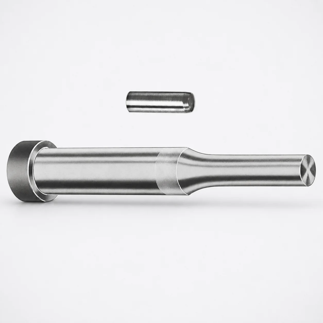
Center Dowel Regular Punches - Metric
Center Dowel Regular Punches - Metric with CRN coating are designed to support stable locating and reliable punch guidance in production tooling. The CRN surface improves resistance to wear for longer service intervals.
- Regular center dowel punch form supports consistent part positioning
- CRN coating enhances wear resistance under repeated forming cycles
- Supports precise assembly with multiple available shank and point options
- Metric tooling standard for use in die sets and punch applications
Specifications
228 configurations available
| Tip shape | D (Shank dia.) (mm) | L1 (Point Length) (mm) | L (Length) (mm) | P Dimension (mm) | W Dimension (mm) | R Dimension (mm) |
|---|---|---|---|---|---|---|
| H | 10 | 19 ~ 25 | 71 ~ 150 | 4 ~ 4.49 | 4 ~ 4.49 | - |
| H | 10 | 19 ~ 25 | 71 ~ 150 | 4 ~ 4.49 | 4.5 ~ 9.95 | - |
| H | 10 | 19 ~ 25 | 71 ~ 150 | 4.5 ~ 9.95 | 4 ~ 4.49 | - |
| H | 10 | 19 ~ 25 | 71 ~ 150 | 4.5 ~ 9.95 | 4.5 ~ 9.95 | - |
| H | 13 | 19 ~ 25 | 71 ~ 150 | 4 ~ 5.99 | 4 ~ 5.99 | - |
| H | 13 | 19 ~ 25 | 71 ~ 150 | 4 ~ 5.99 | 6 ~ 12.95 | - |
| H | 13 | 19 ~ 25 | 71 ~ 150 | 6 ~ 12.95 | 4 ~ 5.99 | - |
| H | 13 | 19 ~ 25 | 71 ~ 150 | 6 ~ 12.95 | 6 ~ 12.95 | - |
| H | 16 | 19 ~ 25 | 71 ~ 150 | 6 ~ 7.19 | 6 ~ 7.19 | - |
| H | 16 | 19 ~ 25 | 71 ~ 150 | 6 ~ 7.19 | 7.2 ~ 15.95 | - |
| H | 16 | 19 ~ 25 | 71 ~ 150 | 7.2 ~ 15.95 | 6 ~ 7.19 | - |
| H | 16 | 19 ~ 25 | 71 ~ 150 | 7.2 ~ 15.95 | 7.2 ~ 15.95 | - |
| H | 20 | 19 ~ 25 | 71 ~ 150 | 6 ~ 7.99 | 6 ~ 7.99 | - |
| H | 20 | 19 ~ 25 | 71 ~ 150 | 6 ~ 7.99 | 8 ~ 19.95 | - |
| H | 20 | 19 ~ 25 | 71 ~ 150 | 8 ~ 19.95 | 6 ~ 7.99 | - |
| H | 20 | 19 ~ 25 | 71 ~ 150 | 8 ~ 19.95 | 8 ~ 19.95 | - |
| H | 25 | 19 ~ 25 | 71 ~ 150 | 6 ~ 8.99 | 6 ~ 8.99 | - |
| H | 25 | 19 ~ 25 | 71 ~ 150 | 6 ~ 8.99 | 9 ~ 24.95 | - |
| H | 25 | 19 ~ 25 | 71 ~ 150 | 9 ~ 24.95 | 6 ~ 8.99 | - |
| H | 25 | 19 ~ 25 | 71 ~ 150 | 9 ~ 24.95 | 9 ~ 24.95 | - |
| H | 32 | 25 ~ 30 | 71 ~ 150 | 7.2 ~ 9.99 | 7.2 ~ 9.99 | - |
| H | 32 | 25 ~ 30 | 71 ~ 150 | 7.2 ~ 9.99 | 10 ~ 31.95 | - |
| H | 32 | 25 ~ 30 | 71 ~ 150 | 10 ~ 31.95 | 7.2 ~ 9.99 | - |
| H | 32 | 25 ~ 30 | 71 ~ 150 | 10 ~ 31.95 | 10 ~ 31.95 | - |
| J | 10 | 19 ~ 25 | 71 ~ 150 | 4 ~ 4.49 | 4 ~ 4.49 | - |
| J | 10 | 19 ~ 25 | 71 ~ 150 | 4 ~ 4.49 | 4.5 ~ 9.95 | - |
| J | 10 | 19 ~ 25 | 71 ~ 150 | 4.5 ~ 9.95 | 4 ~ 4.49 | - |
| J | 10 | 19 ~ 25 | 71 ~ 150 | 4.5 ~ 9.95 | 4.5 ~ 9.95 | - |
| J | 13 | 19 ~ 25 | 71 ~ 150 | 4 ~ 5.99 | 4 ~ 5.99 | - |
| J | 13 | 19 ~ 25 | 71 ~ 150 | 4 ~ 5.99 | 6 ~ 12.95 | - |
| J | 13 | 19 ~ 25 | 71 ~ 150 | 6 ~ 12.95 | 4 ~ 5.99 | - |
| J | 13 | 19 ~ 25 | 71 ~ 150 | 6 ~ 12.95 | 6 ~ 12.95 | - |
| J | 16 | 19 ~ 25 | 71 ~ 150 | 6 ~ 7.19 | 6 ~ 7.19 | - |
| J | 16 | 19 ~ 25 | 71 ~ 150 | 6 ~ 7.19 | 7.2 ~ 15.95 | - |
| J | 16 | 19 ~ 25 | 71 ~ 150 | 7.2 ~ 15.95 | 6 ~ 7.19 | - |
| J | 16 | 19 ~ 25 | 71 ~ 150 | 7.2 ~ 15.95 | 7.2 ~ 15.95 | - |
| J | 20 | 19 ~ 25 | 71 ~ 150 | 6 ~ 7.99 | 6 ~ 7.99 | - |
| J | 20 | 19 ~ 25 | 71 ~ 150 | 6 ~ 7.99 | 8 ~ 19.95 | - |
| J | 20 | 19 ~ 25 | 71 ~ 150 | 8 ~ 19.95 | 6 ~ 7.99 | - |
| J | 20 | 19 ~ 25 | 71 ~ 150 | 8 ~ 19.95 | 8 ~ 19.95 | - |
| J | 25 | 19 ~ 25 | 71 ~ 150 | 6 ~ 8.99 | 6 ~ 8.99 | - |
| J | 25 | 19 ~ 25 | 71 ~ 150 | 6 ~ 8.99 | 9 ~ 24.95 | - |
| J | 25 | 19 ~ 25 | 71 ~ 150 | 9 ~ 24.95 | 6 ~ 8.99 | - |
| J | 25 | 19 ~ 25 | 71 ~ 150 | 9 ~ 24.95 | 9 ~ 24.95 | - |
| J | 32 | 25 ~ 30 | 71 ~ 150 | 7.2 ~ 9.99 | 7.2 ~ 9.99 | - |
| J | 32 | 25 ~ 30 | 71 ~ 150 | 7.2 ~ 9.99 | 10 ~ 31.95 | - |
| J | 32 | 25 ~ 30 | 71 ~ 150 | 10 ~ 31.95 | 7.2 ~ 9.99 | - |
| J | 32 | 25 ~ 30 | 71 ~ 150 | 10 ~ 31.95 | 10 ~ 31.95 | - |
| K | 10 | 19 ~ 25 | 71 ~ 150 | 4 ~ 4.49 | 4 ~ 4.49 | 0.2 ~ 4.975 |
| K | 10 | 19 ~ 25 | 71 ~ 150 | 4 ~ 4.49 | 4.5 ~ 9.95 | 0.2 ~ 4.975 |
Product Guide
Application Scenarios+
This metric center dowel punch is used inside injection and compression die sets where repeatable alignment between the punch assembly and the mating plate is critical. In production tooling, it helps maintain punch guidance during high-cycle molding, reducing drift that can cause part variation and surface defects.
Common scenarios include automotive connector and bracket housings, where consistent cavity/punch alignment supports stable cosmetic and dimensional outcomes. Another application is appliance and consumer electronics housings, where locating stability helps the tooling survive frequent start-stop production. For medical device components requiring tight assembly repeatability, the controlled geometry and wear-focused surface treatment support longer service intervals between regrind or refurbishment.
The CRN-coated variant is suited for these environments because it improves resistance to wear under repeated forming and alignment forces, helping the punch maintain positional reliability over time. Select the point/tip geometry and shank diameter from the available metric ranges to match your guide height and engagement needs.
Material & Process Details+
The provided datasheet specifies a CRN coating for improved wear performance, but it does not list the underlying steel grade or hardness (HRC) values. Because the core material and heat-treatment state are not given, hardness, toughness trade-offs, and specific heat treatment details (e.g., quench & temper, nitriding) cannot be stated from the available information.
What can be confirmed: the CRN-coated surface is intended to increase wear resistance during repeated punch guidance and locating cycles. This typically benefits applications with frequent tool actuation, where sliding/impact contact accelerates wear on dowel surfaces.
- Coating focus: CRN for improved wear resistance and longer service intervals.
- Trade-off note: Without base material and HRC data, toughness vs. wear balance cannot be quantified for this SKU.
- Steel grade comparison: Not provided—if multiple steels are offered for this series, request the material certificate for confirmation.
Sizing & Selection Guide+
Select the center dowel punch dimensions to match the mating locating features in your mold insert, ensuring proper engagement depth and guidance without interference.
Shank diameter (D, mm): choose from 10, 13, 16, 20, 25, 32 based on the bore/guide hole size in the die set. Use the correct point/tip shape (H, J, K, L, N, O, R, V, X, Y, Z) to suit your contact geometry and alignment strategy.
Point length (L1, mm): select from 19–25 or 25–30 to achieve the required contact/locating travel. The overall length (L, mm) is fixed across the series as 71–150, so choose a length that fits the stack height and allows full seating.
- P dimension (mm): available 4–16
- W dimension (mm): available 4–10
- R dimension (mm): available in the listed ranges (0.2–4.975 up to 0.2–15.975 depending on configuration)
Because tolerance and fit values are not provided, confirm clearance/press-fit requirements with your mold design drawings or purchase spec; match dimensions primarily to the functional locating surfaces, then verify interference at max assembly and thermal expansion.
Frequently Asked Questions
How do I choose the correct shank diameter (D) for a center dowel punch in my mold guide hole?+
What are the point length (L1) ranges, and how do they affect locating engagement?+
Which tip shape (H/J/K/L/N/O/R/V/X/Y/Z) should I select for punch guidance and part alignment?+
What does the CRN coating improve, and how does it relate to tool wear during production?+
How should I select overall punch length (L) to match mold stack-up and avoid interference?+
Related Products

Metric Center Dowel Ejector Punches (SKD11 Equivalent)

Dicoat Treatment SKD11 Steel Center Dowel Ejector Punches - Metric

Center Dowel Ejector Punches - Metric, XCN TiCN Coating

DIN Standard SKD11 Steel Gas Release Single-Stepped Ejector Punches

Center Dowel Ejector Punches with Locating Dowel Hole

DIN Standard TiCN Center Dowel Ejector Punches
Need Custom Specifications?
Our engineering team can help with custom configurations, material selection, and volume pricing.