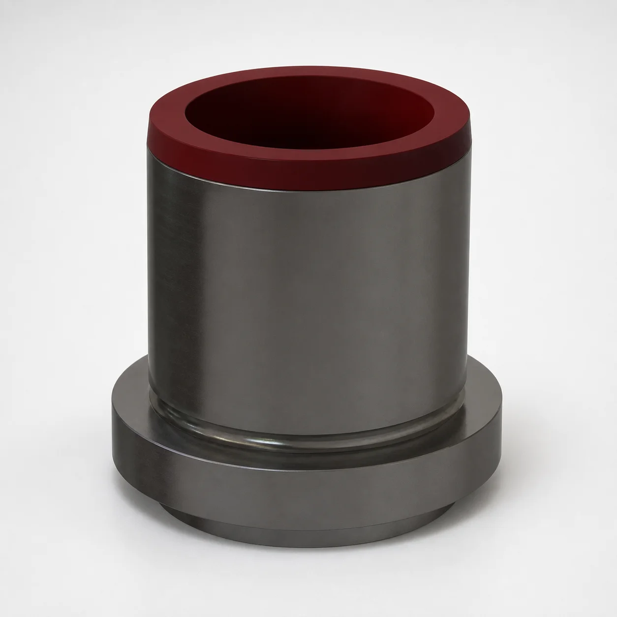
Standard Headed Guide Bushings DC-DGBWF
Standard headed guide bushings DC-DGBWF by DAYTON use low-friction composite material to limit dust and abrasion adhesion, helping reduce abrasive wear and extend service life in forming tools.
- Headed guide bushing geometry supports stable alignment for sliding mold components.
- Low coefficient of friction composite design reduces dust buildup and wear.
- Long operating capability for demanding environments up to 390°C process temperature.
- Built for guide and sliding applications where abrasive conditions and contamination are common.
Specifications
27 configurations available
| D (mm) | Process Temperature (°C) |
|---|---|
| 25 | Up to 160 |
| 25 | Up to 110 |
| 25 | Up to 390 |
| 32 | Up to 160 |
| 32 | Up to 110 |
| 32 | Up to 390 |
| 40 | Up to 160 |
| 40 | Up to 110 |
| 40 | Up to 390 |
| 50 | Up to 160 |
| 50 | Up to 110 |
| 50 | Up to 390 |
| 63 | Up to 160 |
| 63 | Up to 110 |
| 63 | Up to 390 |
| 80 | Up to 160 |
| 80 | Up to 110 |
| 80 | Up to 390 |
| 100 | Up to 160 |
| 100 | Up to 110 |
| 100 | Up to 390 |
| 125 | Up to 160 |
| 125 | Up to 110 |
| 125 | Up to 390 |
| 160 | Up to 160 |
| 160 | Up to 110 |
| 160 | Up to 390 |
Product Guide
Application Scenarios+
In injection mold tooling, standard headed guide bushings DC-DGBWF are used to maintain precise alignment between fixed and moving mold members during cycling. Their headed geometry supports stable guidance for leader/slider components, which helps reduce side-loads that can accelerate wear.
Common scenarios include forming and stamping tools where abrasive particulate and contamination are present. The low-friction composite interface is suited for applications that see dust and debris, helping limit abrasion and adhesion so the guide system maintains consistent movement.
- Automotive component mold bases: suited for leader-driven ejector/slider assemblies requiring stable alignment under continuous operation.
- High-contamination forming tooling: appropriate where abrasive wear is a dominant failure mode and dust management is critical.
- Hot-process environments: applicable when process temperature requirements reach up to 390°C.
Choose this variant when long service life and smooth sliding under dusty or abrasive conditions are priorities.
Material & Process Details+
This bushing is designed around a low-friction composite material used on the sliding interface. In guide and sliding applications, the composite helps reduce dust and abrasion adhesion, improving wear resistance compared with purely metal-on-metal guidance.
Because the provided data focuses on application performance rather than an exact alloy grade, the specific steel grade and resulting heat-treatment state (for example, quenched & tempered or nitrided) are not specified in the input. Heat capability is characterized by the process temperature limits: configurations rated up to 390°C support operation in hotter forming and injection environments, with lower ratings noted for other conditions (up to 160°C and up to 110°C).
- Wear resistance vs. toughness trade-off: composite sliding surfaces generally improve wear under contamination, while the guiding structure still relies on the underlying bushing body for mechanical toughness.
- Hardness (HRC): not provided in the input data, so HRC values should be confirmed from the manufacturer spec sheet before final qualification.
Sizing & Selection Guide+
Selection starts with the bushing’s primary diameter, D, which is specified as 25 ~ 160 mm. Match this diameter to the leader shaft or the corresponding guide bore design dimension so the sliding interface can form the intended fit.
Next, verify the required operating temperature against the provided process limits. Options are listed as up to 160°C, up to 110°C, or up to 390°C; choose the configuration that meets or exceeds your mold’s actual guide operating temperature.
- Cavity/core compatibility: ensure the headed geometry clears surrounding mold hardware and that the bushing length matches the axial guidance zone in your core/cavity stack.
- Tolerance and fit: the input data does not include tolerance bands, so follow your moldmaker’s standard fit practice for guide bushings (shaft/bore clearance and alignment) and confirm fit tolerances with the supplier for the chosen D range.
- Configurable vs. fixed dimensions: D is variable within 25–160 mm; temperature rating is a configuration attribute selected based on your thermal requirements.
Frequently Asked Questions
Which process temperature rating should I use for a mold with hot forming cycles?+
How do I size D for leader/guide alignment in an injection mold assembly?+
Why is the composite low-friction design helpful in dusty or abrasive forming tools?+
Do I need to worry about the underlying steel grade and heat treatment when selecting this bushing?+
Is this bushing intended only for guide systems, or can it be used in other sliding mold components?+
Related Products
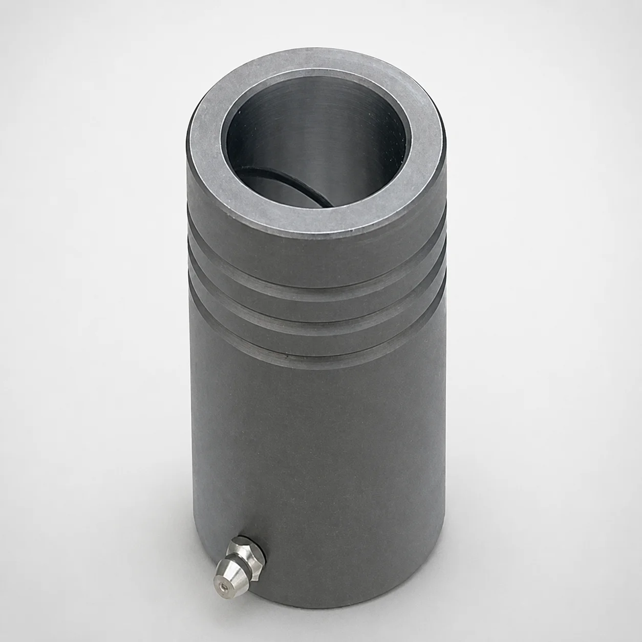
MDB Type Plain Guide Bushings for Die Sets (Oil Groove) Bonded by Devcon Adhesive
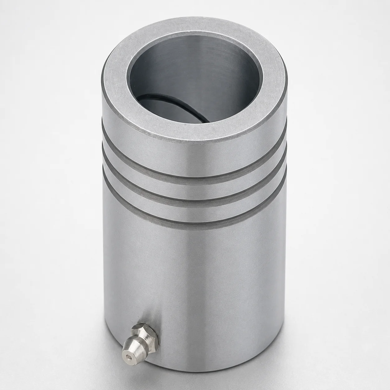
LDB Plain Guide Bushings for Die Sets
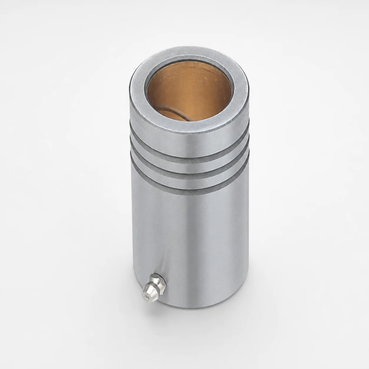
LFB Plain Guide Bushings for Die Sets with Oil Groove, Loctite Adhesive
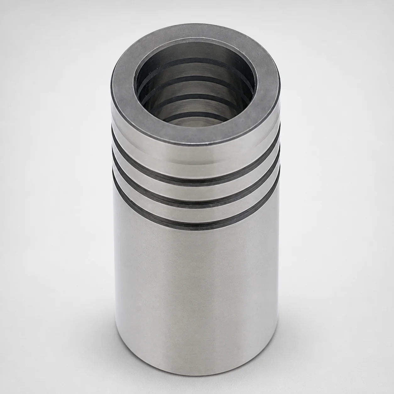
DIN Standard Oil-Free Plain Guide Bushings LDBZ
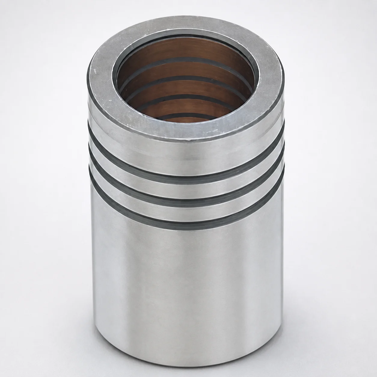
LFBZ Plain Guide Bushings for Die Sets (Oil-Free Copper Alloy) Loctite Bonded
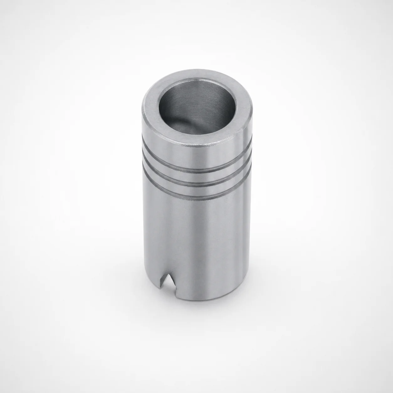
Plain Guide Bushings for Die Sets LDB
Need Custom Specifications?
Our engineering team can help with custom configurations, material selection, and volume pricing.