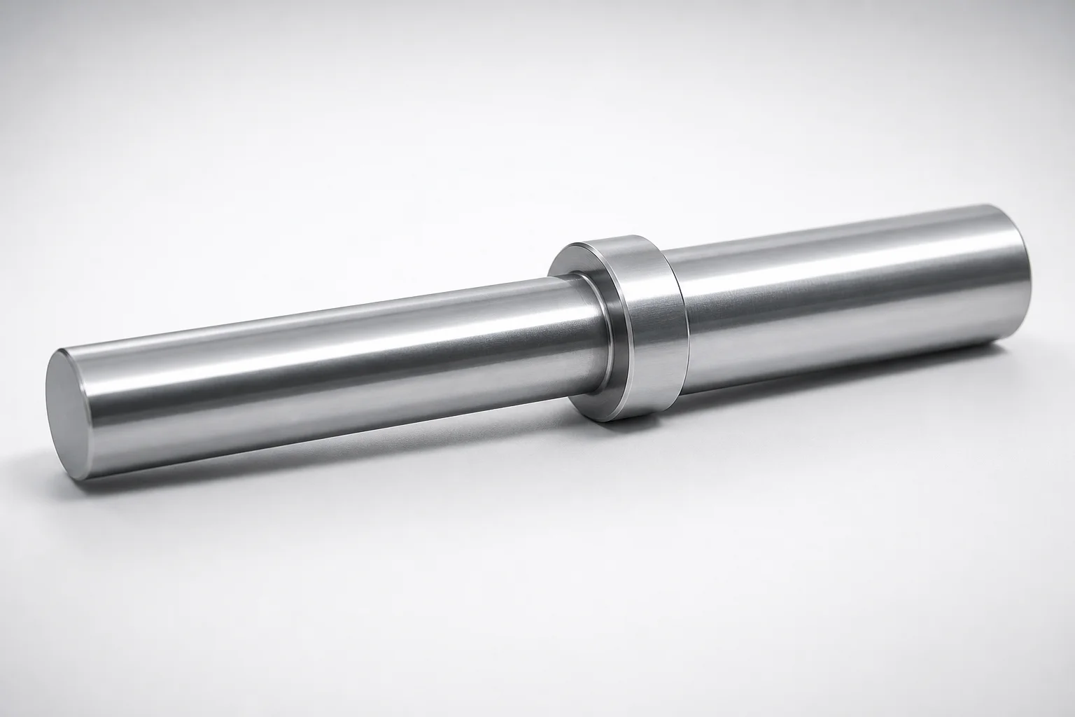
Pusher Pins with Spring Guide Feature
Pusher Pins with Spring Guide Feature are designed for controlled insertion and removal, improving alignment and positioning during assembly operations. The spring-guide function supports stable handling for repeatable performance in industrial mechanisms.
- Spring guide feature helps ensure reliable alignment and consistent positioning
- Supports smooth press-fit behavior to reduce friction and handling variation
- Durable construction helps minimize wear and protect sensitive components
- Suitable for precision assembly tasks in manufacturing and mechanical equipment
Specifications
14 configurations available
| P (Tip diameter) (mm) | P (Tip diameter) tolerance | B (P dimension length) (mm) | L (L dimension) (mm) | type |
|---|---|---|---|---|
| 2 | 0/-0.005 | 5 ~ 20 | 18 ~ 45 | - |
| 2.5 | 0/-0.005 | 5 ~ 20 | 18 ~ 45 | - |
| 3 | 0/-0.005 | 5 ~ 20 | 18 ~ 45 | - |
| 3.5 | 0/-0.005 | 5 ~ 40 | 18 ~ 60 | - |
| 4 | 0/-0.005 | 5 ~ 40 | 18 ~ 60 | - |
| 5 | 0/-0.005 | 5 ~ 40 | 18 ~ 60 | - |
| 6 | 0/-0.005 | 5 ~ 40 | 18 ~ 60 | - |
| 2 | -0.01/-0.02 | 5 ~ 20 | 18 ~ 45 | - |
| 2.5 | -0.01/-0.02 | 5 ~ 20 | 18 ~ 45 | - |
| 3 | -0.01/-0.02 | 5 ~ 20 | 18 ~ 45 | - |
| 3.5 | -0.01/-0.02 | 5 ~ 40 | 18 ~ 60 | - |
| 4 | -0.01/-0.02 | 5 ~ 40 | 18 ~ 60 | - |
| 5 | -0.01/-0.02 | 5 ~ 40 | 18 ~ 60 | - |
| 6 | -0.01/-0.02 | 5 ~ 40 | 18 ~ 60 | - |
Product Guide
Application Scenarios+
Where it’s used: This pusher pin with spring-guide feature is commonly applied in injection mold ejector systems and precision assembly mechanisms where part movement must stay aligned during cycling.
- Automotive and appliance subassemblies: Use it to drive small components through aligned press-fit or insertion steps. The spring-guide helps maintain coaxial positioning so each cycle repeats the same travel and reduces scuffing on mating features.
- Electronics enclosure and connector housings: Suitable for molds that require smooth, low-variation insertion to avoid cosmetic or functional misalignment. Stable guidance improves repeatable positioning during assembly and helps reduce downtime from sticking or debris sensitivity.
- Small medical device housings and housings with tight fit: The controlled insertion/removal behavior supports consistent part handling in compact layouts, improving reliability over long runs.
Why this variant fits: The spring-guide feature improves alignment reliability and repeatable positioning, while smooth insertion reduces friction-related wear and variation—key for tight tolerances and frequent mold cycles.
Material & Process Details+
The provided product data specifies dimensional ranges and tolerances, but it does not list a steel grade, heat treatment state, or surface treatment. Therefore, material properties such as HRC, wear resistance, and toughness trade-offs cannot be stated for this exact SKU from the given information.
How to approach material selection in tooling:
- For high-cycle ejector use, engineers typically choose tool steels selected for balanced wear resistance and toughness; final selection should match mold steel environment and expected cycle count.
- If the pin is specified by your supplier/manufacturer documentation with a steel grade (e.g., SKD61/H13 class for hot-work applications or SKH51/M2 class for high-wear cutting tools), then hardness and heat-treatment (such as quench & temper or nitriding) can be verified against the provided datasheet.
- Any nitriding/carburizing specification should be confirmed because it strongly affects surface wear resistance without proportionally increasing core brittleness.
Sizing & Selection Guide+
Key dimensions to match: This pusher pin family is defined by the tip diameter P = 2 ~ 6 mm, tip diameter tolerance options 0/-0.005 and -0.01/-0.02, plus two length dimensions: B = 5 ~ 20 mm or B = 5 ~ 40 mm, and L = 18 ~ 45 mm or L = 18 ~ 60 mm.
- Select P first: Choose a tip diameter that matches the mating bore/guide feature in your mold or assembly mechanism. Ensure the intended clearance/interference relationship is compatible with the listed tolerance (e.g., tighter negative tolerance supports more controlled fit outcomes).
- Match B and L to travel and packaging: Use B to set the effective guide/engagement length, and L to satisfy overall stroke and cavity/core thickness constraints.
- Check fit behavior: Because tolerances are specified as negative deviations (e.g., 0/-0.005), confirm that minimum diameter will still provide the required guidance without excessive play or binding.
- Configurable vs fixed: The ranges indicate configurable sizes within the specified intervals; confirm the exact variant number for your required combination of P, B, and L.
Frequently Asked Questions
How do I select the correct tip diameter P for a mold guide or ejector hole, given the tolerance options?+
What should I use for B vs. L when designing ejector alignment and packaging space?+
How does the spring guide feature affect wear and cycle-to-cycle positioning in injection molding?+
Can I assume a specific steel grade and hardness for this pusher pin from the provided specifications?+
What dimensional combination of P, B, and L is most suitable for tight-fit alignment needs?+
Need Custom Specifications?
Our engineering team can help with custom configurations, material selection, and volume pricing.