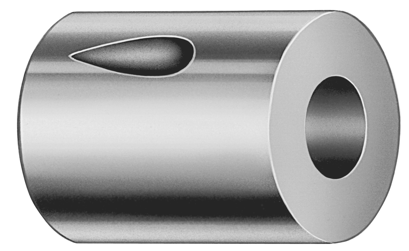
Slug Control Ball Lock Die Buttons - Inch
Inch slug control ball lock die buttons with XN DayTride® coating are designed to help locate mold components reliably while supporting repeatable die engagement in production. The ball-lock action improves setup stability during cycling.
- Ball lock slug control supports stable die positioning for repeatable engagement
- XN DayTride® coating helps reduce friction and wear in high-cycle use
- Works with configurable tip shapes (X/O/R/K/H/J/N/V/Y/Z) for fit and function
- Suitable for die sets requiring controlled slug movement and dependable alignment
Specifications
278 configurations available
| Tip Shape | D (Outer dia.) (in) | L (Length) (coded inch) | P Dimension (in) | W Dimension (in) | R Dimension (in) | Slug control - Material thickness (in) | Slug control - Clearance per side (%) |
|---|---|---|---|---|---|---|---|
| H | 50 (0.5000") | 118 | 0.048 ~ 0.195 | 0.048 ~ 0.195 | - | 0.001 ~ 0.4 | 1 ~ 25 |
| H | 50 (0.5000") | 118 | 0.048 ~ 0.195 | 0.1951 ~ 0.25 | - | 0.001 ~ 0.4 | 1 ~ 25 |
| H | 50 (0.5000") | 118 | 0.1951 ~ 0.25 | 0.048 ~ 0.195 | - | 0.001 ~ 0.4 | 1 ~ 25 |
| H | 50 (0.5000") | 118 | 0.1951 ~ 0.25 | 0.1951 ~ 0.25 | - | 0.001 ~ 0.4 | 1 ~ 25 |
| H | 62 (0.6250") | 118 | 0.064 ~ 0.285 | 0.064 ~ 0.285 | - | 0.001 ~ 0.4 | 1 ~ 25 |
| H | 62 (0.6250") | 118 | 0.064 ~ 0.285 | 0.2851 ~ 0.344 | - | 0.001 ~ 0.4 | 1 ~ 25 |
| H | 62 (0.6250") | 118 | 0.2851 ~ 0.344 | 0.064 ~ 0.285 | - | 0.001 ~ 0.4 | 1 ~ 25 |
| H | 62 (0.6250") | 118 | 0.2851 ~ 0.344 | 0.2851 ~ 0.344 | - | 0.001 ~ 0.4 | 1 ~ 25 |
| H | 75 (0.7500") | 118 | 0.095 ~ 0.345 | 0.095 ~ 0.345 | - | 0.001 ~ 0.4 | 1 ~ 25 |
| H | 75 (0.7500") | 118 | 0.095 ~ 0.345 | 0.3451 ~ 0.453 | - | 0.001 ~ 0.4 | 1 ~ 25 |
| H | 75 (0.7500") | 118 | 0.3451 ~ 0.453 | 0.095 ~ 0.345 | - | 0.001 ~ 0.4 | 1 ~ 25 |
| H | 75 (0.7500") | 118 | 0.3451 ~ 0.453 | 0.3451 ~ 0.453 | - | 0.001 ~ 0.4 | 1 ~ 25 |
| H | 87 (0.8750") | 118 | 0.125 ~ 0.435 | 0.125 ~ 0.435 | - | 0.001 ~ 0.4 | 1 ~ 25 |
| H | 87 (0.8750") | 118 | 0.125 ~ 0.435 | 0.4351 ~ 0.562 | - | 0.001 ~ 0.4 | 1 ~ 25 |
| H | 87 (0.8750") | 118 | 0.4351 ~ 0.562 | 0.125 ~ 0.435 | - | 0.001 ~ 0.4 | 1 ~ 25 |
| H | 87 (0.8750") | 118 | 0.4351 ~ 0.562 | 0.4351 ~ 0.562 | - | 0.001 ~ 0.4 | 1 ~ 25 |
| H | 100 (1.0000") | 118 | 0.125 ~ 0.545 | 0.125 ~ 0.545 | - | 0.001 ~ 0.4 | 1 ~ 25 |
| H | 100 (1.0000") | 118 | 0.125 ~ 0.545 | 0.5451 ~ 0.656 | - | 0.001 ~ 0.4 | 1 ~ 25 |
| H | 100 (1.0000") | 118 | 0.5451 ~ 0.656 | 0.125 ~ 0.545 | - | 0.001 ~ 0.4 | 1 ~ 25 |
| H | 100 (1.0000") | 118 | 0.5451 ~ 0.656 | 0.5451 ~ 0.656 | - | 0.001 ~ 0.4 | 1 ~ 25 |
| H | 125 (1.2500") | 118 | 0.187 ~ 0.655 | 0.187 ~ 0.655 | - | 0.001 ~ 0.4 | 1 ~ 25 |
| H | 125 (1.2500") | 118 | 0.187 ~ 0.655 | 0.6551 ~ 0.75 | - | 0.001 ~ 0.4 | 1 ~ 25 |
| H | 125 (1.2500") | 118 | 0.6551 ~ 0.75 | 0.187 ~ 0.655 | - | 0.001 ~ 0.4 | 1 ~ 25 |
| H | 125 (1.2500") | 118 | 0.6551 ~ 0.75 | 0.6551 ~ 0.75 | - | 0.001 ~ 0.4 | 1 ~ 25 |
| H | 150 (1.5000") | 118 | 0.7801 ~ 0.935 | 0.7801 ~ 0.935 | - | 0.001 ~ 0.4 | 1 ~ 25 |
| H | 150 (1.5000") | 118 | 0.7801 ~ 0.935 | 0.187 ~ 0.78 | - | 0.001 ~ 0.4 | 1 ~ 25 |
| H | 150 (1.5000") | 118 | 0.187 ~ 0.78 | 0.7801 ~ 0.935 | - | 0.001 ~ 0.4 | 1 ~ 25 |
| H | 150 (1.5000") | 118 | 0.187 ~ 0.78 | 0.187 ~ 0.78 | - | 0.001 ~ 0.4 | 1 ~ 25 |
| H | 175 (1.7500") | 118 | 0.187 ~ 1.035 | 0.187 ~ 1.035 | - | 0.001 ~ 0.4 | 1 ~ 25 |
| H | 175 (1.7500") | 118 | 0.187 ~ 1.035 | 1.0351 ~ 1.2 | - | 0.001 ~ 0.4 | 1 ~ 25 |
| H | 175 (1.7500") | 118 | 1.0351 ~ 1.2 | 0.187 ~ 1.035 | - | 0.001 ~ 0.4 | 1 ~ 25 |
| H | 175 (1.7500") | 118 | 1.0351 ~ 1.2 | 1.0351 ~ 1.2 | - | 0.001 ~ 0.4 | 1 ~ 25 |
| J | 50 (0.5000") | 118 | 0.048 ~ 0.195 | 0.048 ~ 0.195 | - | 0.001 ~ 0.4 | 1 ~ 25 |
| J | 50 (0.5000") | 118 | 0.048 ~ 0.195 | 0.1951 ~ 0.25 | - | 0.001 ~ 0.4 | 1 ~ 25 |
| J | 50 (0.5000") | 118 | 0.1951 ~ 0.25 | 0.048 ~ 0.195 | - | 0.001 ~ 0.4 | 1 ~ 25 |
| J | 50 (0.5000") | 118 | 0.1951 ~ 0.25 | 0.1951 ~ 0.25 | - | 0.001 ~ 0.4 | 1 ~ 25 |
| J | 62 (0.6250") | 118 | 0.064 ~ 0.285 | 0.064 ~ 0.285 | - | 0.001 ~ 0.4 | 1 ~ 25 |
| J | 62 (0.6250") | 118 | 0.064 ~ 0.285 | 0.2851 ~ 0.344 | - | 0.001 ~ 0.4 | 1 ~ 25 |
| J | 62 (0.6250") | 118 | 0.2851 ~ 0.344 | 0.064 ~ 0.285 | - | 0.001 ~ 0.4 | 1 ~ 25 |
| J | 62 (0.6250") | 118 | 0.2851 ~ 0.344 | 0.2851 ~ 0.344 | - | 0.001 ~ 0.4 | 1 ~ 25 |
| J | 75 (0.7500") | 118 | 0.095 ~ 0.345 | 0.095 ~ 0.345 | - | 0.001 ~ 0.4 | 1 ~ 25 |
| J | 75 (0.7500") | 118 | 0.095 ~ 0.345 | 0.3451 ~ 0.453 | - | 0.001 ~ 0.4 | 1 ~ 25 |
| J | 75 (0.7500") | 118 | 0.3451 ~ 0.453 | 0.095 ~ 0.345 | - | 0.001 ~ 0.4 | 1 ~ 25 |
| J | 75 (0.7500") | 118 | 0.3451 ~ 0.453 | 0.3451 ~ 0.453 | - | 0.001 ~ 0.4 | 1 ~ 25 |
| J | 87 (0.8750") | 118 | 0.125 ~ 0.435 | 0.125 ~ 0.435 | - | 0.001 ~ 0.4 | 1 ~ 25 |
| J | 87 (0.8750") | 118 | 0.125 ~ 0.435 | 0.4351 ~ 0.562 | - | 0.001 ~ 0.4 | 1 ~ 25 |
| J | 87 (0.8750") | 118 | 0.4351 ~ 0.562 | 0.125 ~ 0.435 | - | 0.001 ~ 0.4 | 1 ~ 25 |
| J | 87 (0.8750") | 118 | 0.4351 ~ 0.562 | 0.4351 ~ 0.562 | - | 0.001 ~ 0.4 | 1 ~ 25 |
| J | 100 (1.0000") | 118 | 0.125 ~ 0.545 | 0.125 ~ 0.545 | - | 0.001 ~ 0.4 | 1 ~ 25 |
| J | 100 (1.0000") | 118 | 0.125 ~ 0.545 | 0.5451 ~ 0.656 | - | 0.001 ~ 0.4 | 1 ~ 25 |
Product Guide
Application Scenarios+
These inch slug control ball lock die buttons are used in injection mold tooling where repeatable die engagement and consistent component alignment are critical. The ball-lock action helps stabilize positioning during repeated press cycles, reducing the risk of drift between mating mold halves.
- Automotive connector and terminal molds: ideal for die sets that require controlled slug movement and dependable alignment under high-cycle operation, helping maintain predictable engagement and return.
- Electronics enclosure and small housing molds: suitable when tight setup repeatability is needed for locating features while maintaining smooth movement during cycling.
- Packaging or consumer product molds: works well when quick, reliable die alignment is required to minimize downtime during changeovers.
The XN DayTride® coating is specifically suited for these applications because it supports lower friction and wear in high-cycle use, helping preserve performance over time. Tip shapes (H/J/K/N/O/R/V/X/Y/Z) further allow engineers to match functional geometry to the mating slug control interface.
Material & Process Details+
This product is specified for use with XN DayTride® coating and a slug control material thickness of 0.001–0.4 in, enabling a coating-to-interface configuration that supports consistent sliding and wear control. While the provided data does not list the underlying steel grade, the engineering intent is a wear-stable, low-friction die locating element for repeated cycling.
- Coating function: XN DayTride® is intended to reduce friction and wear during high-cycle operation, improving longevity of the ball lock engagement surface.
- Wear vs. toughness trade-off: for slug control systems, maintaining stable clearance and managing side wear is often more impactful than maximizing bulk hardness; coating performance is the key contributor for durability in the provided specifications.
- Heat treatment: the input data does not provide quench/temper, nitriding, or target hardness (HRC), so these parameters should be confirmed for the specific supply configuration.
If multiple base materials are available for the slug control insert in your application, select based on required wear life and acceptable compliance, then validate against the specified clearance per side (1–25%).
Sizing & Selection Guide+
To select the correct ball lock die button, match the D (outer diameter) 50–175 in and the functional interface geometry to your die set’s slug control requirements. The L (length) is fixed at coded inch 118, so you should focus selection on outer diameter, tip geometry, and the slug control thickness/clearance.
- Outer diameter: choose D = 50–175 in to fit the locating bore or pocket in the die block while maintaining sufficient material around the feature.
- Interface dimensions: ensure compatibility of P and W within 0.048–1.0351 in and verify the R dimension at 0.007 in for the specified tip radius/transition.
- Clearance per side: set the slug control clearance target using 1–25% to tune the controlled slug movement and alignment stability.
- Material thickness: confirm the slug control thickness is 0.001–0.4 in to achieve the intended engagement feel and return behavior.
Tip shape is variable (H/J/K/N/O/R/V/X/Y/Z), so select the shape that matches your mating geometry; since tolerance values are not provided in the input, verify fit by dimension checks against your mold cavity/core tolerancing requirements.
Frequently Asked Questions
Which tip shapes are available for the inch slug control ball lock die buttons, and how do I choose among H/J/K/N/O/R/V/X/Y/Z?+
What size parameters are fixed vs. configurable when selecting this ball lock die button?+
How do I select the correct slug control clearance per side for stable die engagement?+
Does XN DayTride® coating affect wear life, and what parameter should I validate for high-cycle use?+
What should I check to ensure the ball lock die button fits my die block pocket given the D range?+
Related Products


Need Custom Specifications?
Our engineering team can help with custom configurations, material selection, and volume pricing.