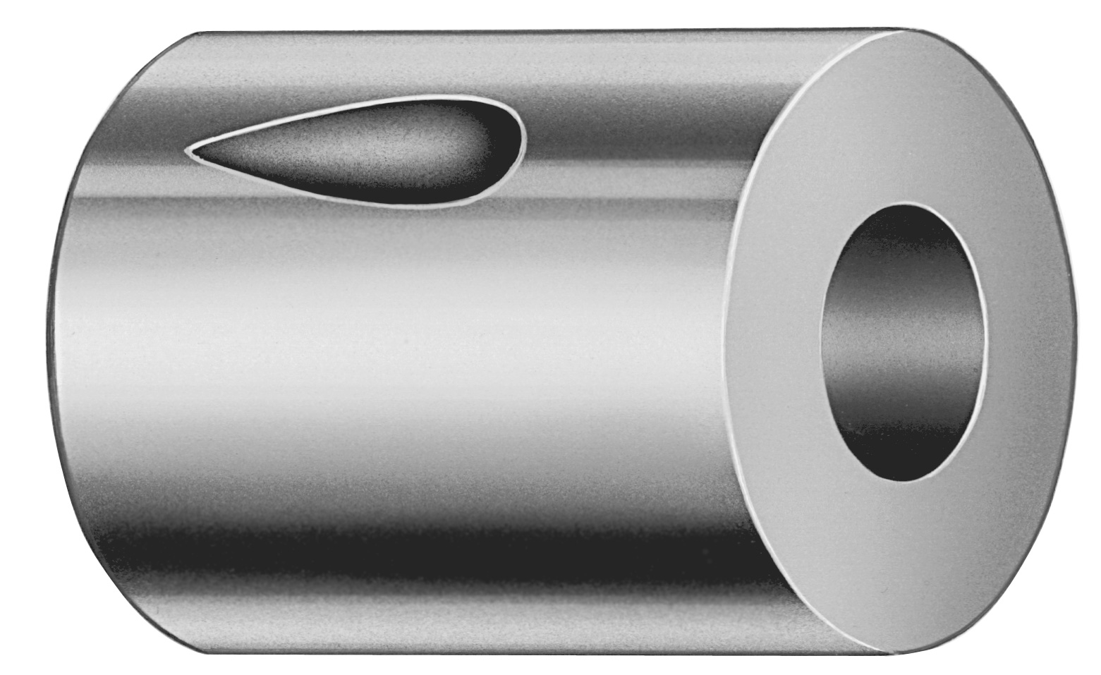
Inch Slug Control Ball Lock Die Buttons with XN DayTride Coa
Inch slug control ball lock die buttons with XN DayTride® coating are designed to help locate mold components reliably while supporting repeatable die engagement in production. The ball-lock action improves setup stability during cycling.
- Ball lock slug control supports stable die positioning for repeatable engagement
- XN DayTride® coating helps reduce friction and wear in high-cycle use
- Works with configurable tip shapes (X/O/R/K/H/J/N/V/Y/Z) for fit and function
- Suitable for die sets requiring controlled slug movement and dependable alignment
Specifications
278 configurations available
| Tip Shape | D (Outer dia.) (in) | L (Length) (coded inch) | P Dimension (in) | W Dimension (in) | R Dimension (in) | Slug control - Material thickness (in) | Slug control - Clearance per side (%) |
|---|---|---|---|---|---|---|---|
| H | 50 (0.5000") | 118 | 0.048 ~ 0.195 | 0.048 ~ 0.195 | - | 0.001 ~ 0.4 | 1 ~ 25 |
| H | 50 (0.5000") | 118 | 0.048 ~ 0.195 | 0.1951 ~ 0.25 | - | 0.001 ~ 0.4 | 1 ~ 25 |
| H | 50 (0.5000") | 118 | 0.1951 ~ 0.25 | 0.048 ~ 0.195 | - | 0.001 ~ 0.4 | 1 ~ 25 |
| H | 50 (0.5000") | 118 | 0.1951 ~ 0.25 | 0.1951 ~ 0.25 | - | 0.001 ~ 0.4 | 1 ~ 25 |
| H | 62 (0.6250") | 118 | 0.064 ~ 0.285 | 0.064 ~ 0.285 | - | 0.001 ~ 0.4 | 1 ~ 25 |
| H | 62 (0.6250") | 118 | 0.064 ~ 0.285 | 0.2851 ~ 0.344 | - | 0.001 ~ 0.4 | 1 ~ 25 |
| H | 62 (0.6250") | 118 | 0.2851 ~ 0.344 | 0.064 ~ 0.285 | - | 0.001 ~ 0.4 | 1 ~ 25 |
| H | 62 (0.6250") | 118 | 0.2851 ~ 0.344 | 0.2851 ~ 0.344 | - | 0.001 ~ 0.4 | 1 ~ 25 |
| H | 75 (0.7500") | 118 | 0.095 ~ 0.345 | 0.095 ~ 0.345 | - | 0.001 ~ 0.4 | 1 ~ 25 |
| H | 75 (0.7500") | 118 | 0.095 ~ 0.345 | 0.3451 ~ 0.453 | - | 0.001 ~ 0.4 | 1 ~ 25 |
| H | 75 (0.7500") | 118 | 0.3451 ~ 0.453 | 0.095 ~ 0.345 | - | 0.001 ~ 0.4 | 1 ~ 25 |
| H | 75 (0.7500") | 118 | 0.3451 ~ 0.453 | 0.3451 ~ 0.453 | - | 0.001 ~ 0.4 | 1 ~ 25 |
| H | 87 (0.8750") | 118 | 0.125 ~ 0.435 | 0.125 ~ 0.435 | - | 0.001 ~ 0.4 | 1 ~ 25 |
| H | 87 (0.8750") | 118 | 0.125 ~ 0.435 | 0.4351 ~ 0.562 | - | 0.001 ~ 0.4 | 1 ~ 25 |
| H | 87 (0.8750") | 118 | 0.4351 ~ 0.562 | 0.125 ~ 0.435 | - | 0.001 ~ 0.4 | 1 ~ 25 |
| H | 87 (0.8750") | 118 | 0.4351 ~ 0.562 | 0.4351 ~ 0.562 | - | 0.001 ~ 0.4 | 1 ~ 25 |
| H | 100 (1.0000") | 118 | 0.125 ~ 0.545 | 0.125 ~ 0.545 | - | 0.001 ~ 0.4 | 1 ~ 25 |
| H | 100 (1.0000") | 118 | 0.125 ~ 0.545 | 0.5451 ~ 0.656 | - | 0.001 ~ 0.4 | 1 ~ 25 |
| H | 100 (1.0000") | 118 | 0.5451 ~ 0.656 | 0.125 ~ 0.545 | - | 0.001 ~ 0.4 | 1 ~ 25 |
| H | 100 (1.0000") | 118 | 0.5451 ~ 0.656 | 0.5451 ~ 0.656 | - | 0.001 ~ 0.4 | 1 ~ 25 |
| H | 125 (1.2500") | 118 | 0.187 ~ 0.655 | 0.187 ~ 0.655 | - | 0.001 ~ 0.4 | 1 ~ 25 |
| H | 125 (1.2500") | 118 | 0.187 ~ 0.655 | 0.6551 ~ 0.75 | - | 0.001 ~ 0.4 | 1 ~ 25 |
| H | 125 (1.2500") | 118 | 0.6551 ~ 0.75 | 0.187 ~ 0.655 | - | 0.001 ~ 0.4 | 1 ~ 25 |
| H | 125 (1.2500") | 118 | 0.6551 ~ 0.75 | 0.6551 ~ 0.75 | - | 0.001 ~ 0.4 | 1 ~ 25 |
| H | 150 (1.5000") | 118 | 0.7801 ~ 0.935 | 0.7801 ~ 0.935 | - | 0.001 ~ 0.4 | 1 ~ 25 |
| H | 150 (1.5000") | 118 | 0.7801 ~ 0.935 | 0.187 ~ 0.78 | - | 0.001 ~ 0.4 | 1 ~ 25 |
| H | 150 (1.5000") | 118 | 0.187 ~ 0.78 | 0.7801 ~ 0.935 | - | 0.001 ~ 0.4 | 1 ~ 25 |
| H | 150 (1.5000") | 118 | 0.187 ~ 0.78 | 0.187 ~ 0.78 | - | 0.001 ~ 0.4 | 1 ~ 25 |
| H | 175 (1.7500") | 118 | 0.187 ~ 1.035 | 0.187 ~ 1.035 | - | 0.001 ~ 0.4 | 1 ~ 25 |
| H | 175 (1.7500") | 118 | 0.187 ~ 1.035 | 1.0351 ~ 1.2 | - | 0.001 ~ 0.4 | 1 ~ 25 |
| H | 175 (1.7500") | 118 | 1.0351 ~ 1.2 | 0.187 ~ 1.035 | - | 0.001 ~ 0.4 | 1 ~ 25 |
| H | 175 (1.7500") | 118 | 1.0351 ~ 1.2 | 1.0351 ~ 1.2 | - | 0.001 ~ 0.4 | 1 ~ 25 |
| J | 50 (0.5000") | 118 | 0.048 ~ 0.195 | 0.048 ~ 0.195 | - | 0.001 ~ 0.4 | 1 ~ 25 |
| J | 50 (0.5000") | 118 | 0.048 ~ 0.195 | 0.1951 ~ 0.25 | - | 0.001 ~ 0.4 | 1 ~ 25 |
| J | 50 (0.5000") | 118 | 0.1951 ~ 0.25 | 0.048 ~ 0.195 | - | 0.001 ~ 0.4 | 1 ~ 25 |
| J | 50 (0.5000") | 118 | 0.1951 ~ 0.25 | 0.1951 ~ 0.25 | - | 0.001 ~ 0.4 | 1 ~ 25 |
| J | 62 (0.6250") | 118 | 0.064 ~ 0.285 | 0.064 ~ 0.285 | - | 0.001 ~ 0.4 | 1 ~ 25 |
| J | 62 (0.6250") | 118 | 0.064 ~ 0.285 | 0.2851 ~ 0.344 | - | 0.001 ~ 0.4 | 1 ~ 25 |
| J | 62 (0.6250") | 118 | 0.2851 ~ 0.344 | 0.064 ~ 0.285 | - | 0.001 ~ 0.4 | 1 ~ 25 |
| J | 62 (0.6250") | 118 | 0.2851 ~ 0.344 | 0.2851 ~ 0.344 | - | 0.001 ~ 0.4 | 1 ~ 25 |
| J | 75 (0.7500") | 118 | 0.095 ~ 0.345 | 0.095 ~ 0.345 | - | 0.001 ~ 0.4 | 1 ~ 25 |
| J | 75 (0.7500") | 118 | 0.095 ~ 0.345 | 0.3451 ~ 0.453 | - | 0.001 ~ 0.4 | 1 ~ 25 |
| J | 75 (0.7500") | 118 | 0.3451 ~ 0.453 | 0.095 ~ 0.345 | - | 0.001 ~ 0.4 | 1 ~ 25 |
| J | 75 (0.7500") | 118 | 0.3451 ~ 0.453 | 0.3451 ~ 0.453 | - | 0.001 ~ 0.4 | 1 ~ 25 |
| J | 87 (0.8750") | 118 | 0.125 ~ 0.435 | 0.125 ~ 0.435 | - | 0.001 ~ 0.4 | 1 ~ 25 |
| J | 87 (0.8750") | 118 | 0.125 ~ 0.435 | 0.4351 ~ 0.562 | - | 0.001 ~ 0.4 | 1 ~ 25 |
| J | 87 (0.8750") | 118 | 0.4351 ~ 0.562 | 0.125 ~ 0.435 | - | 0.001 ~ 0.4 | 1 ~ 25 |
| J | 87 (0.8750") | 118 | 0.4351 ~ 0.562 | 0.4351 ~ 0.562 | - | 0.001 ~ 0.4 | 1 ~ 25 |
| J | 100 (1.0000") | 118 | 0.125 ~ 0.545 | 0.125 ~ 0.545 | - | 0.001 ~ 0.4 | 1 ~ 25 |
| J | 100 (1.0000") | 118 | 0.125 ~ 0.545 | 0.5451 ~ 0.656 | - | 0.001 ~ 0.4 | 1 ~ 25 |
Product Guide
Application Scenarios+
Slug control ball lock die buttons are used in injection mold tool builds where the die needs consistent alignment and repeatable engagement during high-cycle production. This design is well-suited for automotive connector and insert molds, where tight positional repeatability helps maintain stable gate and cavity relationships despite thermal expansion.
The XN DayTride® coated surface variant is also advantageous for consumer electronics housing molds with frequent cycling, because reduced friction can improve return smoothness and help manage wear on the locating interface.
For medical device and labware mold assemblies, ball-lock action supports controlled slug movement and dependable alignment when the tooling requires predictable engagement after ejector actuation. Select the appropriate tip shape (H/J/K/N/O/R/V/X/Y/Z) to match your die engagement geometry and ensure the slug control behavior is consistent with your cavity/core layout.
- Use in die sets requiring controlled slug movement and stable repeatability
- Coating supports reduced friction and wear in cycling conditions
- Tip shape selection enables fit to existing engagement features
Material & Process Details+
Material and heat-treatment details are not specified in the provided data. What is specified is the slug control material thickness, which ranges from 0.001 to 0.4 in, and the side clearance per 1 to 25%. These parameters directly influence stiffness, wear behavior at the locating interface, and the trade-off between compliance (to accommodate tolerance stack-up) and positional rigidity.
The XN DayTride® coating is the key surface technology for this variant. In high-cycle molds, a low-friction coating helps reduce sliding/impact wear on the die button locating surfaces, supporting quicker, more consistent return after each cycle.
- Thickness (0.001–0.4 in): thicker slug control generally increases rigidity but may reduce tolerance accommodation
- Clearance per side (1–25%): higher clearance improves compliance, lower clearance improves positional tightness
If you need a specific steel grade, hardness target (HRC), or nitriding/quench-and-temper requirement, confirm these details with your tooling material specification because they are not contained in the current product metadata.
Sizing & Selection Guide+
Use the fixed and variable dimensions to match the ball lock die button to your mold’s die engagement features. This series uses a fixed length L = 118 (coded inch), so selection focuses on outer diameter and engagement geometry.
Choose D (outer diameter) within 50–175 in based on available pocket space and the required locating contact area. Select a compatible tip shape from H, J, K, N, O, R, V, X, Y, Z to align with your core/cavity engagement design.
For the slug control behavior, set the P and W dimensions within 0.048–1.0351 in (both are variable in this range) to match your internal engagement or clearance geometry. The slug control material thickness is 0.001–0.4 in, and the clearance per side is 1–25%—use these to manage tolerance stack-up while maintaining repeatable die engagement.
- Match D and tip shape to physical space and mating geometry
- Use P/W and clearance % to balance tight alignment vs. compliance
- L is fixed (coded inch 118), so do not change length during selection
Frequently Asked Questions
Which tip shapes are available for these inch slug control ball lock die buttons?+
What are the allowable outer diameter and engagement dimensions for correct fit in the mold?+
How do slug control thickness and clearance per side affect die alignment repeatability?+
What does the XN DayTride® coating change for high-cycle injection mold use?+
Is there a specified steel grade or hardness (HRC) for these die buttons in the provided data?+
Related Products


Need Custom Specifications?
Our engineering team can help with custom configurations, material selection, and volume pricing.