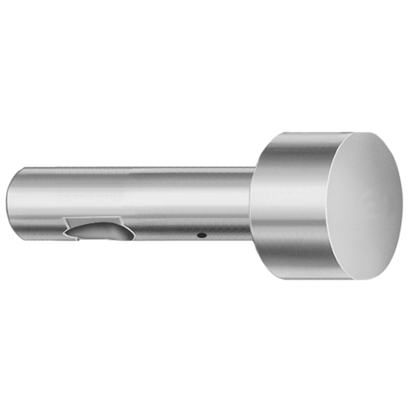
Ball Lock Ejector Punches Light Duty Inch X-Shaped Tip
Ball Lock Ejector Punches (X-shaped tip) are built for light-duty applications in inch tooling, combining a reliable ball-lock head with a point larger than the shank for consistent locating and ejection stability.
- Point larger than shank design for secure ball-lock retention
- X-shaped tip geometry supports controlled die entry and release
- Standardized part formatting for streamlined engineering selection
- For press tooling, dies, and position-critical ejection systems
Specifications
114 configurations available
| Tip Shape | D (Shank dia.) (in) | L (Length) (coded inch) | P Dimension (in) | W Dimension (in) | R Dimension (in) |
|---|---|---|---|---|---|
| H | 37 (0.3750") | 250 ~ 450 | 0.376 ~ 0.875 | 0.062 ~ 0.124 | - |
| H | 37 (0.3750") | 250 ~ 450 | 0.376 ~ 0.875 | 0.125 ~ 0.875 | - |
| H | 50 (0.5000") | 250 ~ 450 | 0.501 ~ 1.25 | 0.158 ~ 0.187 | - |
| H | 50 (0.5000") | 250 ~ 450 | 0.501 ~ 1.25 | 0.188 ~ 1.25 | - |
| H | 62 (0.6250") | 250 ~ 450 | 0.626 ~ 1.5 | 0.25 ~ 1.5 | - |
| H | 62 (0.6250") | 250 ~ 450 | 0.626 ~ 1.5 | 0.158 ~ 0.249 | - |
| H | 75 (0.7500") | 250 ~ 450 | 0.751 ~ 1.5 | 0.235 ~ 0.311 | - |
| H | 75 (0.7500") | 250 ~ 450 | 0.751 ~ 1.5 | 0.312 ~ 1.5 | - |
| H | 87 (0.8750") | 250 ~ 450 | 0.876 ~ 1.75 | 0.235 ~ 0.374 | - |
| H | 87 (0.8750") | 250 ~ 450 | 0.876 ~ 1.75 | 0.375 ~ 1.75 | - |
| H | 100 (1.0000") | 250 ~ 450 | 1.001 ~ 1.75 | 0.235 ~ 0.436 | - |
| H | 100 (1.0000") | 250 ~ 450 | 1.001 ~ 1.75 | 0.437 ~ 1.75 | - |
| J | 37 (0.3750") | 250 ~ 450 | 0.376 ~ 0.875 | 0.062 ~ 0.124 | - |
| J | 37 (0.3750") | 250 ~ 450 | 0.376 ~ 0.875 | 0.125 ~ 0.875 | - |
| J | 50 (0.5000") | 250 ~ 450 | 0.501 ~ 1.25 | 0.158 ~ 0.187 | - |
| J | 50 (0.5000") | 250 ~ 450 | 0.501 ~ 1.25 | 0.188 ~ 1.25 | - |
| J | 62 (0.6250") | 250 ~ 450 | 0.626 ~ 1.5 | 0.25 ~ 1.5 | - |
| J | 62 (0.6250") | 250 ~ 450 | 0.626 ~ 1.5 | 0.158 ~ 0.249 | - |
| J | 75 (0.7500") | 250 ~ 450 | 0.751 ~ 1.5 | 0.235 ~ 0.311 | - |
| J | 75 (0.7500") | 250 ~ 450 | 0.751 ~ 1.5 | 0.312 ~ 1.5 | - |
| J | 87 (0.8750") | 250 ~ 450 | 0.876 ~ 1.75 | 0.235 ~ 0.374 | - |
| J | 87 (0.8750") | 250 ~ 450 | 0.876 ~ 1.75 | 0.375 ~ 1.75 | - |
| J | 100 (1.0000") | 250 ~ 450 | 1.001 ~ 1.75 | 0.235 ~ 0.436 | - |
| J | 100 (1.0000") | 250 ~ 450 | 1.001 ~ 1.75 | 0.437 ~ 1.75 | - |
| K | 37 (0.3750") | 250 ~ 450 | 0.376 ~ 0.875 | 0.062 ~ 0.124 | 0.007 ~ 0.4375 |
| K | 37 (0.3750") | 250 ~ 450 | 0.376 ~ 0.875 | 0.125 ~ 0.875 | 0.007 ~ 0.4375 |
| K | 50 (0.5000") | 250 ~ 450 | 0.501 ~ 1.25 | 0.158 ~ 0.187 | 0.007 ~ 0.625 |
| K | 50 (0.5000") | 250 ~ 450 | 0.501 ~ 1.25 | 0.188 ~ 1.25 | 0.007 ~ 0.625 |
| K | 62 (0.6250") | 250 ~ 450 | 0.626 ~ 1.5 | 0.25 ~ 1.5 | 0.007 ~ 0.75 |
| K | 62 (0.6250") | 250 ~ 450 | 0.626 ~ 1.5 | 0.158 ~ 0.249 | 0.007 ~ 0.75 |
| K | 75 (0.7500") | 250 ~ 450 | 0.751 ~ 1.5 | 0.235 ~ 0.311 | 0.007 ~ 0.75 |
| K | 75 (0.7500") | 250 ~ 450 | 0.751 ~ 1.5 | 0.312 ~ 1.5 | 0.007 ~ 0.75 |
| K | 87 (0.8750") | 250 ~ 450 | 0.876 ~ 1.75 | 0.235 ~ 0.374 | 0.007 ~ 0.875 |
| K | 87 (0.8750") | 250 ~ 450 | 0.876 ~ 1.75 | 0.375 ~ 1.75 | 0.007 ~ 0.875 |
| K | 100 (1.0000") | 250 ~ 450 | 1.001 ~ 1.75 | 0.235 ~ 0.436 | 0.007 ~ 0.875 |
| K | 100 (1.0000") | 250 ~ 450 | 1.001 ~ 1.75 | 0.437 ~ 1.75 | 0.007 ~ 0.875 |
| L | 37 (0.3750") | 250 ~ 450 | 0.376 ~ 0.875 | 0.062 ~ 0.124 | - |
| L | 37 (0.3750") | 250 ~ 450 | 0.376 ~ 0.875 | 0.125 ~ 0.875 | - |
| L | 50 (0.5000") | 250 ~ 450 | 0.501 ~ 1.25 | 0.158 ~ 0.187 | - |
| L | 50 (0.5000") | 250 ~ 450 | 0.501 ~ 1.25 | 0.188 ~ 1.25 | - |
| L | 62 (0.6250") | 250 ~ 450 | 0.626 ~ 1.5 | 0.25 ~ 1.5 | - |
| L | 62 (0.6250") | 250 ~ 450 | 0.626 ~ 1.5 | 0.158 ~ 0.249 | - |
| L | 75 (0.7500") | 250 ~ 450 | 0.751 ~ 1.5 | 0.235 ~ 0.311 | - |
| L | 75 (0.7500") | 250 ~ 450 | 0.751 ~ 1.5 | 0.312 ~ 1.5 | - |
| L | 87 (0.8750") | 250 ~ 450 | 0.876 ~ 1.75 | 0.235 ~ 0.374 | - |
| L | 87 (0.8750") | 250 ~ 450 | 0.876 ~ 1.75 | 0.375 ~ 1.75 | - |
| L | 100 (1.0000") | 250 ~ 450 | 1.001 ~ 1.75 | 0.235 ~ 0.436 | - |
| L | 100 (1.0000") | 250 ~ 450 | 1.001 ~ 1.75 | 0.437 ~ 1.75 | - |
| N | 37 (0.3750") | 250 ~ 450 | - | 0.326 ~ 0.758 | - |
| N | 50 (0.5000") | 250 ~ 450 | - | 0.434 ~ 1.083 | - |
Product Guide
Application Scenarios+
Ball-lock ejector punches with an X-shaped tip are used in light-duty inch injection and press tooling where ejector guidance must remain stable during die opening and closing. Their ball-lock head provides reliable retention in the punch housing, helping prevent punch float and misalignment under frequent cycling.
- Die alignment and controlled ejection: In position-critical systems for small inserts or die components, the X-shaped tip geometry supports predictable entry and release at the cavity interface.
- Press tooling for locator-driven assemblies: The point-larger-than-shank locating concept improves stability of the ball-lock engagement while maintaining consistent ejection force transmission in light-duty applications.
- Modular tooling and quick die changes: Standardized inch-based shank diameters and coded lengths simplify engineering selection and compatibility checks across recurring die projects.
This variant is suited to these scenarios because it combines a retention-focused ball-lock design with an X-shaped tip that promotes repeatable die interaction using inch tooling dimensions.
Material & Process Details+
The provided data specifies the geometric and inch sizing features of this light-duty ejector punch system, but it does not include the steel grade, heat-treatment condition, or hardness (HRC). Therefore, material hardness, wear resistance, and toughness trade-offs cannot be stated from the supplied specification.
- Tip shape and engagement behavior: The ball-lock retention and point-larger-than-shank design primarily influence stability and repeatability at the die interface.
- Heat treatment: No quench/temper, nitriding, or pre-hardened state is listed in the input parameters.
- Steel-grade comparison: Since no alternative materials or grades are provided, comparisons (e.g., SKD61 vs. H13, or M2 vs. equivalent) are not supported.
If you can share the actual punch material grade and hardness specification from the product datasheet, the material_html can be updated with accurate heat treatment and HRC-based guidance.
Sizing & Selection Guide+
Select the ejector punch by matching the shank diameter D, coded length L, and tip/point dimensions to the punch housing and cavity/core interaction requirements.
- Shank diameter (D, in): Choose from 37 (0.3750), 50 (0.5000), 62 (0.6250), 75 (0.7500), 87 (0.8750), or 100 (1.0000).
- Length (L coded inch): Use L in the range 250 ~ 450, selecting the coded value that provides the required stick-out while maintaining proper guide engagement.
- Tip/geometry controls: Match P (in) to the available ranges (0.376~0.875, 0.501~1.25, 0.626~1.5, 0.751~1.5, 0.876~1.75, 1.001~1.75) and W (in) to 0.062~0.867. Select R (in) from 0.007~0.4375, 0.007~0.625, 0.007~0.75, or 0.007~0.875 based on your die interface profile.
For ball-lock punches, confirm fit by checking the punch diameter compatibility with the ball-lock pocket/housing dimensions in your die design. Because tolerance values are not provided in the input data, verify tolerances against your housing spec before finalizing the dimension set.
Frequently Asked Questions
Which shank diameter D options are available for these light-duty inch ball-lock ejector punches?+
Shank diameter D is provided in inch sizes: 37 (0.3750"), 50 (0.5000"), 62 (0.6250"), 75 (0.7500"), 87 (0.8750"), and 100 (1.0000").
Choose the diameter that matches the punch housing/guide bore used in your die or press tooling.
What coded length range (L) should be used when selecting the ejector punch for my mold cavity/core depth?+
The punch length (coded inch) L is specified in the range 250 ~ 450.
Select the coded length that delivers the required engagement during ejection while maintaining stable guidance in the housing. Confirm stick-out against your cavity/core geometry.
How do I choose the P, W, and R dimensions for the X-shaped tip interface in my die?+
Use the provided dimension ranges to match your die interface: P (0.376~0.875, 0.501~1.25, 0.626~1.5, 0.751~1.5, 0.876~1.75, 1.001~1.75), W (0.062~0.867), and R (0.007~0.4375, 0.007~0.625, 0.007~0.75, or 0.007~0.875).
Pick the combination that aligns with your punch-to-cavity/core contact profile.
Are different tip shapes (H, J, K, L, N, O, R, V, X, Y, Z) compatible with the ball-lock retention style?+
The input lists multiple Tip Shape options: H, J, K, L, N, O, R, V, X, Y, Z.
All are part of the ball-lock ejector punch family per the category context; however, ensure the chosen tip shape is compatible with your required die-entry/release geometry and the selected P/W/R ranges.
What material grade and hardness (HRC) should I assume for this DAYTON ejector punch variant?+
The supplied product metadata does not include a steel grade, heat-treatment condition, or hardness (HRC) specification.
To avoid mismatches in wear life and toughness, request the material datasheet or grade details for series code 250300512739 before finalizing the design for abrasive or long-cycle duty.
Related Products


Need Custom Specifications?
Our engineering team can help with custom configurations, material selection, and volume pricing.