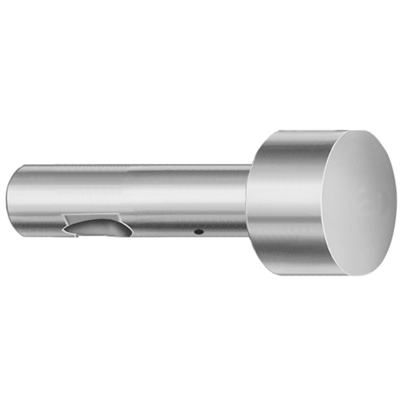
Inch XNP Coating Point Larger than Shank Ball Lock Ejector Punches - Light Duty
Point Larger than Shank Ball Lock ejector punches for inch tooling (XNP coating) deliver stable retention and efficient ejection under light-duty production cycles. Built for repeatable punch performance in precision mold applications.
- Point larger than shank geometry improves guidance and punch stability
- XNP coating supports wear resistance in demanding molding environments
- Inch-coded length options help match standard ejector arrangements
- Engineered for light-duty ejection in ball lock punch assemblies
Specifications
114 configurations available
| Tip Shape | D (Shank dia.) (in) | L (Length) (coded inch) | P Dimension (in) | W Dimension (in) | R Dimension (in) |
|---|---|---|---|---|---|
| H | 37 (0.3750") | 250 ~ 450 | 0.376 ~ 0.875 | 0.062 ~ 0.124 | - |
| H | 37 (0.3750") | 250 ~ 450 | 0.376 ~ 0.875 | 0.125 ~ 0.875 | - |
| H | 50 (0.5000") | 250 ~ 450 | 0.501 ~ 1.25 | 0.158 ~ 0.187 | - |
| H | 50 (0.5000") | 250 ~ 450 | 0.501 ~ 1.25 | 0.188 ~ 1.25 | - |
| H | 62 (0.6250") | 250 ~ 450 | 0.626 ~ 1.5 | 0.25 ~ 1.5 | - |
| H | 62 (0.6250") | 250 ~ 450 | 0.626 ~ 1.5 | 0.158 ~ 0.249 | - |
| H | 75 (0.7500") | 250 ~ 450 | 0.751 ~ 1.5 | 0.235 ~ 0.311 | - |
| H | 75 (0.7500") | 250 ~ 450 | 0.751 ~ 1.5 | 0.312 ~ 1.5 | - |
| H | 87 (0.8750") | 250 ~ 450 | 0.876 ~ 1.75 | 0.235 ~ 0.374 | - |
| H | 87 (0.8750") | 250 ~ 450 | 0.876 ~ 1.75 | 0.375 ~ 1.75 | - |
| H | 100 (1.0000") | 250 ~ 450 | 1.001 ~ 1.75 | 0.235 ~ 0.436 | - |
| H | 100 (1.0000") | 250 ~ 450 | 1.001 ~ 1.75 | 0.437 ~ 1.75 | - |
| J | 37 (0.3750") | 250 ~ 450 | 0.376 ~ 0.875 | 0.062 ~ 0.124 | - |
| J | 37 (0.3750") | 250 ~ 450 | 0.376 ~ 0.875 | 0.125 ~ 0.875 | - |
| J | 50 (0.5000") | 250 ~ 450 | 0.501 ~ 1.25 | 0.158 ~ 0.187 | - |
| J | 50 (0.5000") | 250 ~ 450 | 0.501 ~ 1.25 | 0.188 ~ 1.25 | - |
| J | 62 (0.6250") | 250 ~ 450 | 0.626 ~ 1.5 | 0.25 ~ 1.5 | - |
| J | 62 (0.6250") | 250 ~ 450 | 0.626 ~ 1.5 | 0.158 ~ 0.249 | - |
| J | 75 (0.7500") | 250 ~ 450 | 0.751 ~ 1.5 | 0.235 ~ 0.311 | - |
| J | 75 (0.7500") | 250 ~ 450 | 0.751 ~ 1.5 | 0.312 ~ 1.5 | - |
| J | 87 (0.8750") | 250 ~ 450 | 0.876 ~ 1.75 | 0.235 ~ 0.374 | - |
| J | 87 (0.8750") | 250 ~ 450 | 0.876 ~ 1.75 | 0.375 ~ 1.75 | - |
| J | 100 (1.0000") | 250 ~ 450 | 1.001 ~ 1.75 | 0.235 ~ 0.436 | - |
| J | 100 (1.0000") | 250 ~ 450 | 1.001 ~ 1.75 | 0.437 ~ 1.75 | - |
| K | 37 (0.3750") | 250 ~ 450 | 0.376 ~ 0.875 | 0.062 ~ 0.124 | 0.007 ~ 0.4375 |
| K | 37 (0.3750") | 250 ~ 450 | 0.376 ~ 0.875 | 0.125 ~ 0.875 | 0.007 ~ 0.4375 |
| K | 50 (0.5000") | 250 ~ 450 | 0.501 ~ 1.25 | 0.158 ~ 0.187 | 0.007 ~ 0.625 |
| K | 50 (0.5000") | 250 ~ 450 | 0.501 ~ 1.25 | 0.188 ~ 1.25 | 0.007 ~ 0.625 |
| K | 62 (0.6250") | 250 ~ 450 | 0.626 ~ 1.5 | 0.25 ~ 1.5 | 0.007 ~ 0.75 |
| K | 62 (0.6250") | 250 ~ 450 | 0.626 ~ 1.5 | 0.158 ~ 0.249 | 0.007 ~ 0.75 |
| K | 75 (0.7500") | 250 ~ 450 | 0.751 ~ 1.5 | 0.235 ~ 0.311 | 0.007 ~ 0.75 |
| K | 75 (0.7500") | 250 ~ 450 | 0.751 ~ 1.5 | 0.312 ~ 1.5 | 0.007 ~ 0.75 |
| K | 87 (0.8750") | 250 ~ 450 | 0.876 ~ 1.75 | 0.235 ~ 0.374 | 0.007 ~ 0.875 |
| K | 87 (0.8750") | 250 ~ 450 | 0.876 ~ 1.75 | 0.375 ~ 1.75 | 0.007 ~ 0.875 |
| K | 100 (1.0000") | 250 ~ 450 | 1.001 ~ 1.75 | 0.235 ~ 0.436 | 0.007 ~ 0.875 |
| K | 100 (1.0000") | 250 ~ 450 | 1.001 ~ 1.75 | 0.437 ~ 1.75 | 0.007 ~ 0.875 |
| L | 37 (0.3750") | 250 ~ 450 | 0.376 ~ 0.875 | 0.062 ~ 0.124 | - |
| L | 37 (0.3750") | 250 ~ 450 | 0.376 ~ 0.875 | 0.125 ~ 0.875 | - |
| L | 50 (0.5000") | 250 ~ 450 | 0.501 ~ 1.25 | 0.158 ~ 0.187 | - |
| L | 50 (0.5000") | 250 ~ 450 | 0.501 ~ 1.25 | 0.188 ~ 1.25 | - |
| L | 62 (0.6250") | 250 ~ 450 | 0.626 ~ 1.5 | 0.25 ~ 1.5 | - |
| L | 62 (0.6250") | 250 ~ 450 | 0.626 ~ 1.5 | 0.158 ~ 0.249 | - |
| L | 75 (0.7500") | 250 ~ 450 | 0.751 ~ 1.5 | 0.235 ~ 0.311 | - |
| L | 75 (0.7500") | 250 ~ 450 | 0.751 ~ 1.5 | 0.312 ~ 1.5 | - |
| L | 87 (0.8750") | 250 ~ 450 | 0.876 ~ 1.75 | 0.235 ~ 0.374 | - |
| L | 87 (0.8750") | 250 ~ 450 | 0.876 ~ 1.75 | 0.375 ~ 1.75 | - |
| L | 100 (1.0000") | 250 ~ 450 | 1.001 ~ 1.75 | 0.235 ~ 0.436 | - |
| L | 100 (1.0000") | 250 ~ 450 | 1.001 ~ 1.75 | 0.437 ~ 1.75 | - |
| N | 37 (0.3750") | 250 ~ 450 | - | 0.326 ~ 0.758 | - |
| N | 50 (0.5000") | 250 ~ 450 | - | 0.434 ~ 1.083 | - |
Product Guide
Application Scenarios+
This light-duty ball-lock ejector point is designed for inch-sized injection mold tooling where stable punch guidance and consistent retention are required. The larger-than-shank point geometry helps center the ejector action in ball-lock punch assemblies, reducing wobble and improving repeatability in high-frequency cycles.
Common scenario 1: automotive connector housing molds—use this variant with XNP coating to support wear resistance at the ejector tip during frequent parting and ejection. The point size larger than the shank improves alignment through the mold platen and keeps the ball-lock mechanism working reliably.
Common scenario 2: consumer electronics enclosure molds—the light-duty design is well suited for smaller ejector loads where efficient ejection and dimensional repeatability matter. Select the tip shape and P/W dimensions to match the existing ejector arrangement while maintaining smooth travel.
Common scenario 3: general-purpose plastic components—inch-coded lengths (L) simplify configuration across standard ejector layouts, supporting efficient ejection without over-specifying heavier duty punches.
- XNP coating supports wear resistance for long service life in light-duty applications
- Larger point than shank improves punch stability and guidance during ejection
- Inch-coded length options align with standard ejector arrangements
Material & Process Details+
The provided datasheet for this series focuses on geometric selection and XNP coating usage; it does not specify the underlying steel grade or exact heat treatment cycle. For accurate metallurgy and hardness verification, confirm the steel grade and heat treat status for series code 250300512818 with the supplier documentation.
XNP coating is specified for this light-duty ejector punch point and is intended to improve wear resistance at the contact and sliding regions during repeated ejection. In typical ejector-point applications, the coating enhances surface durability while the core material provides the required toughness for ball-lock retention and mechanical loading.
- Hardness and heat treatment state (e.g., quenched & tempered) are not provided in the input data
- Wear resistance emphasis is driven by XNP coating for light-duty production cycles
- Potential trade-off: higher surface wear resistance coatings can increase surface rigidity; proper sizing (P/W/R) helps maintain smooth guidance
Sizing & Selection Guide+
Select this ball-lock ejector point by matching the shank diameter (D), coded length (L), and the point geometry parameters (P, W, and R) to the mold cavity/core ejector system and the ball-lock pocket design.
- D (shank dia.): choose one of 0.3750" (37), 0.5000" (50), 0.6250" (62), 0.7500" (75), 0.8750" (87), or 1.0000" (100)
- L (Length, coded inch): select within 250 ~ 450 to align with your ejector stack height and ball-lock assembly depth
- P dimension: pick the matching range band—0.376~0.875, 0.501~1.25, 0.626~1.5, 0.751~1.5, 0.876~1.75, or 1.001~1.75
- W dimension: 0.062~0.867
- R dimension: 0.007~0.4375, 0.007~0.625, 0.007~0.75, or 0.007~0.875
To ensure proper fit, verify that your ball-lock punch housing and mating pocket are dimensioned for the chosen D and that the point larger-than-shank profile does not interfere with nearby ejector features. Where your design tolerances are tight, confirm the supplier’s drawing-level tolerances for P/W/R (not provided in the input) before finalizing the cavity/core interface.
Frequently Asked Questions
Which shank diameter (D) range is compatible with my existing ball-lock punch assembly in inch tooling?+
This series offers D (shank dia.) options of 0.3750" (37), 0.5000" (50), 0.6250" (62), 0.7500" (75), 0.8750" (87), and 1.0000" (100). Match the shank diameter to the mating ball-lock pocket so the retention geometry and guidance behavior remain stable during ejection. Confirm that your ejector stack height supports the selected coded length L (250 ~ 450).
How do I select the coded length L (250–450) to avoid interference in the ejector system?+
Use the coded length L within 250 ~ 450 to align with the required ejector travel and assembly depth for your specific mold stack. The point larger-than-shank profile changes the functional engagement area, so ensure there is clearance around the ball-lock head and adjacent features throughout the full stroke. If you have limited space, verify the overall stack-up while using the correct inch-coded length option.
What do the point geometry parameters P, W, and R control, and how do I choose their ranges?+
The P dimension is available in multiple inch range bands: 0.376~0.875, 0.501~1.25, 0.626~1.5, 0.751~1.5, 0.876~1.75, and 1.001~1.75. The W dimension ranges from 0.062~0.867, and R is provided in stepped upper limits such as 0.007~0.4375 up to 0.007~0.875. Choose these ranges to match the contact/guidance profile of your core or ejector contact zone while avoiding collisions during ejection.
Which tip shapes (H, J, K, L, N, O, R, V, X, Y, Z) should I consider for light-duty ejection?+
This series supports multiple tip shapes: H, J, K, L, N, O, R, V, X, Y, Z. Select the tip shape based on the required contact form and how the ejector point engages the parting surface (e.g., flat vs. contoured contact needs). For light-duty cycles, the XNP coating is specified to help maintain wear performance while the geometry selection controls stability.
What material/heat-treatment and hardness can I assume for the XNP-coated ejector point?+
The input data specifies XNP coating but does not provide the underlying steel grade, hardness (HRC), or heat treatment state. To ensure design compliance, request the steel grade and hardness from the series documentation for 250300512818. When you receive hardness and heat-treat details, you can then validate wear resistance expectations versus toughness for your specific cycle load.
Related Products


Need Custom Specifications?
Our engineering team can help with custom configurations, material selection, and volume pricing.