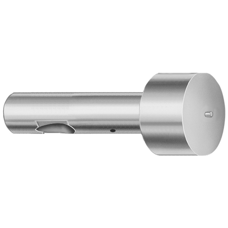
XNAP Coated Point Larger than Shank Ejector Ball Lock Punches - Light Duty
Point larger than shank ejector ball lock punches (XNAP coated) are designed for light duty die tooling where repeatable ball-lock retention and smooth ejection matter. The larger point geometry improves functional stability during punching cycles, especially in smaller press applications.
- Ball-lock punch geometry with larger point for consistent retention
- XNAP coating helps reduce wear and supports smooth operation
- Options for X/R/K/O/H/L/J/N/V/Y/Z tip shapes to match tooling needs
- Typical use in inches die sets for light duty punching and forming
Specifications
114 configurations available
| Tip Shape | D (Shank dia.) (in) | Jektole group | L (Length) (coded inch) | P Dimension (in) | W Dimension (in) | R Dimension (in) |
|---|---|---|---|---|---|---|
| H | 37 (0.3750") | J4 | 250 ~ 450 | 0.376 ~ 0.875 | 0.062 ~ 0.124 | - |
| H | 37 (0.3750") | J4 | 250 ~ 450 | 0.376 ~ 0.875 | 0.125 ~ 0.875 | - |
| H | 50 (0.5000") | J6 | 250 ~ 450 | 0.501 ~ 1.25 | 0.158 ~ 0.187 | - |
| H | 50 (0.5000") | J6 | 250 ~ 450 | 0.501 ~ 1.25 | 0.188 ~ 1.25 | - |
| H | 62 (0.6250") | J6 | 250 ~ 450 | 0.626 ~ 1.5 | 0.25 ~ 1.5 | - |
| H | 62 (0.6250") | J6 | 250 ~ 450 | 0.626 ~ 1.5 | 0.158 ~ 0.249 | - |
| H | 75 (0.7500") | J9 | 250 ~ 450 | 0.751 ~ 1.5 | 0.235 ~ 0.311 | - |
| H | 75 (0.7500") | J9 | 250 ~ 450 | 0.751 ~ 1.5 | 0.312 ~ 1.5 | - |
| H | 87 (0.8750") | J9 | 250 ~ 450 | 0.876 ~ 1.75 | 0.235 ~ 0.374 | - |
| H | 87 (0.8750") | J9 | 250 ~ 450 | 0.876 ~ 1.75 | 0.375 ~ 1.75 | - |
| H | 100 (1.0000") | J9 | 250 ~ 450 | 1.001 ~ 1.75 | 0.235 ~ 0.436 | - |
| H | 100 (1.0000") | J9 | 250 ~ 450 | 1.001 ~ 1.75 | 0.437 ~ 1.75 | - |
| J | 37 (0.3750") | J4 | 250 ~ 450 | 0.376 ~ 0.875 | 0.062 ~ 0.124 | - |
| J | 37 (0.3750") | J4 | 250 ~ 450 | 0.376 ~ 0.875 | 0.125 ~ 0.875 | - |
| J | 50 (0.5000") | J6 | 250 ~ 450 | 0.501 ~ 1.25 | 0.158 ~ 0.187 | - |
| J | 50 (0.5000") | J6 | 250 ~ 450 | 0.501 ~ 1.25 | 0.188 ~ 1.25 | - |
| J | 62 (0.6250") | J6 | 250 ~ 450 | 0.626 ~ 1.5 | 0.25 ~ 1.5 | - |
| J | 62 (0.6250") | J6 | 250 ~ 450 | 0.626 ~ 1.5 | 0.158 ~ 0.249 | - |
| J | 75 (0.7500") | J9 | 250 ~ 450 | 0.751 ~ 1.5 | 0.235 ~ 0.311 | - |
| J | 75 (0.7500") | J9 | 250 ~ 450 | 0.751 ~ 1.5 | 0.312 ~ 1.5 | - |
| J | 87 (0.8750") | J9 | 250 ~ 450 | 0.876 ~ 1.75 | 0.235 ~ 0.374 | - |
| J | 87 (0.8750") | J9 | 250 ~ 450 | 0.876 ~ 1.75 | 0.375 ~ 1.75 | - |
| J | 100 (1.0000") | J9 | 250 ~ 450 | 1.001 ~ 1.75 | 0.235 ~ 0.436 | - |
| J | 100 (1.0000") | J9 | 250 ~ 450 | 1.001 ~ 1.75 | 0.437 ~ 1.75 | - |
| K | 37 (0.3750") | J4 | 250 ~ 450 | 0.376 ~ 0.875 | 0.062 ~ 0.124 | 0.007 ~ 0.4375 |
| K | 37 (0.3750") | J4 | 250 ~ 450 | 0.376 ~ 0.875 | 0.125 ~ 0.875 | 0.007 ~ 0.4375 |
| K | 50 (0.5000") | J6 | 250 ~ 450 | 0.501 ~ 1.25 | 0.158 ~ 0.187 | 0.007 ~ 0.625 |
| K | 50 (0.5000") | J6 | 250 ~ 450 | 0.501 ~ 1.25 | 0.188 ~ 1.25 | 0.007 ~ 0.625 |
| K | 62 (0.6250") | J6 | 250 ~ 450 | 0.626 ~ 1.5 | 0.25 ~ 1.5 | 0.007 ~ 0.75 |
| K | 62 (0.6250") | J6 | 250 ~ 450 | 0.626 ~ 1.5 | 0.158 ~ 0.249 | 0.007 ~ 0.75 |
| K | 75 (0.7500") | J9 | 250 ~ 450 | 0.751 ~ 1.5 | 0.235 ~ 0.311 | 0.007 ~ 0.75 |
| K | 75 (0.7500") | J9 | 250 ~ 450 | 0.751 ~ 1.5 | 0.312 ~ 1.5 | 0.007 ~ 0.75 |
| K | 87 (0.8750") | J9 | 250 ~ 450 | 0.876 ~ 1.75 | 0.235 ~ 0.374 | 0.007 ~ 0.875 |
| K | 87 (0.8750") | J9 | 250 ~ 450 | 0.876 ~ 1.75 | 0.375 ~ 1.75 | 0.007 ~ 0.875 |
| K | 100 (1.0000") | J9 | 250 ~ 450 | 1.001 ~ 1.75 | 0.235 ~ 0.436 | 0.007 ~ 0.875 |
| K | 100 (1.0000") | J9 | 250 ~ 450 | 1.001 ~ 1.75 | 0.437 ~ 1.75 | 0.007 ~ 0.875 |
| L | 37 (0.3750") | J4 | 250 ~ 450 | 0.376 ~ 0.875 | 0.062 ~ 0.124 | - |
| L | 37 (0.3750") | J4 | 250 ~ 450 | 0.376 ~ 0.875 | 0.125 ~ 0.875 | - |
| L | 50 (0.5000") | J6 | 250 ~ 450 | 0.501 ~ 1.25 | 0.158 ~ 0.187 | - |
| L | 50 (0.5000") | J6 | 250 ~ 450 | 0.501 ~ 1.25 | 0.188 ~ 1.25 | - |
| L | 62 (0.6250") | J6 | 250 ~ 450 | 0.626 ~ 1.5 | 0.25 ~ 1.5 | - |
| L | 62 (0.6250") | J6 | 250 ~ 450 | 0.626 ~ 1.5 | 0.158 ~ 0.249 | - |
| L | 75 (0.7500") | J9 | 250 ~ 450 | 0.751 ~ 1.5 | 0.235 ~ 0.311 | - |
| L | 75 (0.7500") | J9 | 250 ~ 450 | 0.751 ~ 1.5 | 0.312 ~ 1.5 | - |
| L | 87 (0.8750") | J9 | 250 ~ 450 | 0.876 ~ 1.75 | 0.235 ~ 0.374 | - |
| L | 87 (0.8750") | J9 | 250 ~ 450 | 0.876 ~ 1.75 | 0.375 ~ 1.75 | - |
| L | 100 (1.0000") | J9 | 250 ~ 450 | 1.001 ~ 1.75 | 0.235 ~ 0.436 | - |
| L | 100 (1.0000") | J9 | 250 ~ 450 | 1.001 ~ 1.75 | 0.437 ~ 1.75 | - |
| N | 37 (0.3750") | J4 | 250 ~ 450 | - | 0.326 ~ 0.758 | - |
| N | 50 (0.5000") | J6 | 250 ~ 450 | - | 0.434 ~ 1.083 | - |
Product Guide
Application Scenarios+
This light-duty ball-lock punchpoint variant is used in injection and die tooling where retention consistency and ejection smoothness are critical. The larger point than the shank helps maintain stable positioning during repeated punching cycles, which is especially helpful in compact press configurations and smaller tooling cavities.
- Automotive interior/trim brackets: supports reliable press-fit retention in thin-to-medium gauge forms where misalignment can accelerate wear at the punch point.
- Appliance housings and small structural stampings: the increased point geometry improves functional stability as parts cycle through progressive or turret stations.
- General light-duty forming and punching fixtures: the XNAP coating is selected to promote smoother ejection and reduce surface wear under intermittent high-contact loads.
Select this configuration when you need predictable ball-lock seating combined with reduced friction at the point, while staying within light-duty tooling requirements.
Material & Process Details+
The provided metadata specifies XNAP coating for light-duty performance; however, no base steel grade or heat-treatment data is included. For accurate hardness, wear-resistance expectations, and compatibility with your press load profile, request the underlying steel and coating thickness from the supplier documentation tied to the specific series code.
- XNAP coating: used to improve sliding behavior and reduce point wear, supporting smoother ejection over repeated cycles.
- Hardness and toughness trade-offs: without the steel grade and heat-treatment state, hardness (HRC) and toughness cannot be verified from the input data; these parameters should be confirmed for your die material and press tonnage.
- Material comparison: if alternative steels or coating systems are offered for other duty ratings, higher-hardness options typically raise wear resistance but can reduce toughness if not tempered appropriately.
Use the tip-shape options (H/J/K/L/N/O/R/V/X/Y/Z) to tune contact geometry, while validating the steel/coating specification for your target life and load conditions.
Sizing & Selection Guide+
Correct selection is driven by matching the shank diameter (D), overall length (L coded inch), and the functional point dimensions (P, W, R) to the corresponding ball-lock punch pocket and clearance conditions in your mold or die set.
- Shank diameter D (in): choose from 0.3750, 0.5000, 0.6250, 0.7500, 0.8750, or 1.0000 depending on the ball-lock retention seat.
- Length L: select from the fixed coded inch range 250 ~ 450 to achieve the required protrusion and safe engagement under your tooling stack-up.
- Point geometry: match P within the available bands (0.376~0.875, 0.501~1.25, 0.626~1.5, 0.751~1.5, 0.876~1.75, 1.001~1.75 in), and pair with the available W (0.062~0.867 in) and R (0.007~0.4375 / 0.007~0.625 / 0.007~0.75 / 0.007~0.875 in) to control tip radius and clearance contact.
Because tolerances are not provided in the input data, verify the manufacturer’s fit tolerances for your punch pocket and retention mechanism before finalizing the cavity/core dimensions. Tip shape selection (H, J, K, L, N, O, R, V, X, Y, Z) should be aligned with your die cutting geometry.
Frequently Asked Questions
Which shank diameter (D) values are available for this light-duty ball-lock punchpoint?+
The available D (shank dia.) options are 0.3750, 0.5000, 0.6250, 0.7500, 0.8750, and 1.0000 in. Select the diameter that matches your ball-lock retention seat and clearance in the die tooling. If your pocket is already machined, confirm fit using the supplier’s tolerance sheet for the final part number.
How do I choose the coded length (L) range for correct engagement in the punch retaining system?+
This product lists a fixed coded inch length range of L = 250 ~ 450. Use it to ensure the punchpoint protrusion reaches the forming or punching interface while maintaining safe engagement with the ball-lock retention mechanism. Because actual protrusion depends on your die stack-up, validate against your tooling drawings and retention depth.
What tip shapes are supported, and when would I choose one over another?+
Supported Tip Shape codes are H, J, K, L, N, O, R, V, X, Y, Z. Choose the shape that best matches your cutting/forming contact geometry and desired clearance characteristics at the point. For ball-lock retention consistency, keep the tip geometry compatible with your die opening and guide features.
What are the available P, W, and R dimension ranges for the point larger than shank configuration?+
The P dimension is available in ranges from 0.376 ~ 0.875, 0.501 ~ 1.25, 0.626 ~ 1.5, 0.751 ~ 1.5, 0.876 ~ 1.75, and 1.001 ~ 1.75 in. W is 0.062 ~ 0.867 in, and R is available in 0.007 ~ 0.4375, 0.007 ~ 0.625, 0.007 ~ 0.75, or 0.007 ~ 0.875 in. Pair these ranges to meet your point radius and clearance requirements for smooth ejection.
Does the XNAP coating choice affect wear and ejection for light-duty tooling?+
Yes. This variant is explicitly listed with an XNAP coating, intended to promote smooth ejection and reduce wear at the point under light-duty contact conditions. If you are targeting higher tonnage or abrasive materials, confirm whether a heavier-duty coated/steel option is required, since base steel and hardness are not specified in the provided data.
Related Products


Need Custom Specifications?
Our engineering team can help with custom configurations, material selection, and volume pricing.