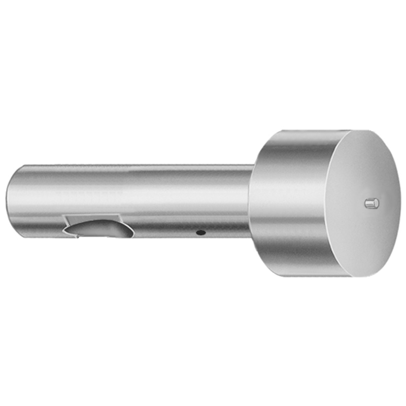
Ball Lock Ejector Punches - Light Duty (XNAD Coating)
Ball Lock Ejector Punches - Light Duty (XNAD coating) are designed for reliable part release in small-to-medium tooling. The ball-lock style point helps lock alignment during cycling while the coating supports wear control.
- Ball-lock ejector punch design improves ejection stability in repeated cycles
- XNAD coating helps reduce wear for consistent punch performance
- Coded inch tooling lengths support efficient fit in standard die sets
- Use in general light-duty molding, forming, and die maintenance applications
Specifications
114 configurations available
| Tip Shape | D (Shank dia.) (in) | Jektole group | L (Length) (coded inch) | P Dimension (in) | W Dimension (in) | R Dimension (in) |
|---|---|---|---|---|---|---|
| H | 37 (0.3750") | J4 | 250 ~ 450 | 0.376 ~ 0.875 | 0.062 ~ 0.124 | - |
| H | 37 (0.3750") | J4 | 250 ~ 450 | 0.376 ~ 0.875 | 0.125 ~ 0.875 | - |
| H | 50 (0.5000") | J6 | 250 ~ 450 | 0.501 ~ 1.25 | 0.158 ~ 0.187 | - |
| H | 50 (0.5000") | J6 | 250 ~ 450 | 0.501 ~ 1.25 | 0.188 ~ 1.25 | - |
| H | 62 (0.6250") | J6 | 250 ~ 450 | 0.626 ~ 1.5 | 0.25 ~ 1.5 | - |
| H | 62 (0.6250") | J6 | 250 ~ 450 | 0.626 ~ 1.5 | 0.158 ~ 0.249 | - |
| H | 75 (0.7500") | J9 | 250 ~ 450 | 0.751 ~ 1.5 | 0.235 ~ 0.311 | - |
| H | 75 (0.7500") | J9 | 250 ~ 450 | 0.751 ~ 1.5 | 0.312 ~ 1.5 | - |
| H | 87 (0.8750") | J9 | 250 ~ 450 | 0.876 ~ 1.75 | 0.235 ~ 0.374 | - |
| H | 87 (0.8750") | J9 | 250 ~ 450 | 0.876 ~ 1.75 | 0.375 ~ 1.75 | - |
| H | 100 (1.0000") | J9 | 250 ~ 450 | 1.001 ~ 1.75 | 0.235 ~ 0.436 | - |
| H | 100 (1.0000") | J9 | 250 ~ 450 | 1.001 ~ 1.75 | 0.437 ~ 1.75 | - |
| J | 37 (0.3750") | J4 | 250 ~ 450 | 0.376 ~ 0.875 | 0.062 ~ 0.124 | - |
| J | 37 (0.3750") | J4 | 250 ~ 450 | 0.376 ~ 0.875 | 0.125 ~ 0.875 | - |
| J | 50 (0.5000") | J6 | 250 ~ 450 | 0.501 ~ 1.25 | 0.158 ~ 0.187 | - |
| J | 50 (0.5000") | J6 | 250 ~ 450 | 0.501 ~ 1.25 | 0.188 ~ 1.25 | - |
| J | 62 (0.6250") | J6 | 250 ~ 450 | 0.626 ~ 1.5 | 0.25 ~ 1.5 | - |
| J | 62 (0.6250") | J6 | 250 ~ 450 | 0.626 ~ 1.5 | 0.158 ~ 0.249 | - |
| J | 75 (0.7500") | J9 | 250 ~ 450 | 0.751 ~ 1.5 | 0.235 ~ 0.311 | - |
| J | 75 (0.7500") | J9 | 250 ~ 450 | 0.751 ~ 1.5 | 0.312 ~ 1.5 | - |
| J | 87 (0.8750") | J9 | 250 ~ 450 | 0.876 ~ 1.75 | 0.235 ~ 0.374 | - |
| J | 87 (0.8750") | J9 | 250 ~ 450 | 0.876 ~ 1.75 | 0.375 ~ 1.75 | - |
| J | 100 (1.0000") | J9 | 250 ~ 450 | 1.001 ~ 1.75 | 0.235 ~ 0.436 | - |
| J | 100 (1.0000") | J9 | 250 ~ 450 | 1.001 ~ 1.75 | 0.437 ~ 1.75 | - |
| K | 37 (0.3750") | J4 | 250 ~ 450 | 0.376 ~ 0.875 | 0.062 ~ 0.124 | 0.007 ~ 0.4375 |
| K | 37 (0.3750") | J4 | 250 ~ 450 | 0.376 ~ 0.875 | 0.125 ~ 0.875 | 0.007 ~ 0.4375 |
| K | 50 (0.5000") | J6 | 250 ~ 450 | 0.501 ~ 1.25 | 0.158 ~ 0.187 | 0.007 ~ 0.625 |
| K | 50 (0.5000") | J6 | 250 ~ 450 | 0.501 ~ 1.25 | 0.188 ~ 1.25 | 0.007 ~ 0.625 |
| K | 62 (0.6250") | J6 | 250 ~ 450 | 0.626 ~ 1.5 | 0.25 ~ 1.5 | 0.007 ~ 0.75 |
| K | 62 (0.6250") | J6 | 250 ~ 450 | 0.626 ~ 1.5 | 0.158 ~ 0.249 | 0.007 ~ 0.75 |
| K | 75 (0.7500") | J9 | 250 ~ 450 | 0.751 ~ 1.5 | 0.235 ~ 0.311 | 0.007 ~ 0.75 |
| K | 75 (0.7500") | J9 | 250 ~ 450 | 0.751 ~ 1.5 | 0.312 ~ 1.5 | 0.007 ~ 0.75 |
| K | 87 (0.8750") | J9 | 250 ~ 450 | 0.876 ~ 1.75 | 0.235 ~ 0.374 | 0.007 ~ 0.875 |
| K | 87 (0.8750") | J9 | 250 ~ 450 | 0.876 ~ 1.75 | 0.375 ~ 1.75 | 0.007 ~ 0.875 |
| K | 100 (1.0000") | J9 | 250 ~ 450 | 1.001 ~ 1.75 | 0.235 ~ 0.436 | 0.007 ~ 0.875 |
| K | 100 (1.0000") | J9 | 250 ~ 450 | 1.001 ~ 1.75 | 0.437 ~ 1.75 | 0.007 ~ 0.875 |
| L | 37 (0.3750") | J4 | 250 ~ 450 | 0.376 ~ 0.875 | 0.062 ~ 0.124 | - |
| L | 37 (0.3750") | J4 | 250 ~ 450 | 0.376 ~ 0.875 | 0.125 ~ 0.875 | - |
| L | 50 (0.5000") | J6 | 250 ~ 450 | 0.501 ~ 1.25 | 0.158 ~ 0.187 | - |
| L | 50 (0.5000") | J6 | 250 ~ 450 | 0.501 ~ 1.25 | 0.188 ~ 1.25 | - |
| L | 62 (0.6250") | J6 | 250 ~ 450 | 0.626 ~ 1.5 | 0.25 ~ 1.5 | - |
| L | 62 (0.6250") | J6 | 250 ~ 450 | 0.626 ~ 1.5 | 0.158 ~ 0.249 | - |
| L | 75 (0.7500") | J9 | 250 ~ 450 | 0.751 ~ 1.5 | 0.235 ~ 0.311 | - |
| L | 75 (0.7500") | J9 | 250 ~ 450 | 0.751 ~ 1.5 | 0.312 ~ 1.5 | - |
| L | 87 (0.8750") | J9 | 250 ~ 450 | 0.876 ~ 1.75 | 0.235 ~ 0.374 | - |
| L | 87 (0.8750") | J9 | 250 ~ 450 | 0.876 ~ 1.75 | 0.375 ~ 1.75 | - |
| L | 100 (1.0000") | J9 | 250 ~ 450 | 1.001 ~ 1.75 | 0.235 ~ 0.436 | - |
| L | 100 (1.0000") | J9 | 250 ~ 450 | 1.001 ~ 1.75 | 0.437 ~ 1.75 | - |
| N | 37 (0.3750") | J4 | 250 ~ 450 | - | 0.326 ~ 0.758 | - |
| N | 50 (0.5000") | J6 | 250 ~ 450 | - | 0.434 ~ 1.083 | - |
Product Guide
Application Scenarios+
Ball-lock ejector punches are used in injection molding and die-casting systems where stable part release depends on repeatable punch alignment. The ball-lock style point helps maintain lock-up position during cycling, reducing misalignment-driven wear and improving ejection consistency in compact tooling layouts.
- Die casting and small-to-medium molded housings: Choose this light-duty variant with an XNAD coating to support wear control at the punch face during frequent starts/stops.
- Automotive interior/consumer components: The alignment-stabilizing ball-lock geometry supports predictable ejection for thin features and frequent molding cycles.
- Die maintenance and forming fixtures: Coded inch tooling lengths (L = 250–450) help match standard die set conventions for efficient retrofit and replacement.
With its light-duty intent and wear-supporting coating, this configuration is suited to applications that require consistent ejection without the highest mass-load conditions of heavy-duty ejectors.
Material & Process Details+
The provided metadata specifies the XNAD coating as the key surface technology for this light-duty ball-lock ejector punch. XNAD is selected to improve wear resistance at the contact and sliding surfaces, supporting more consistent punch performance across repeated ejection cycles.
- Wear resistance vs. toughness: Coatings typically enhance surface hardness/tribology, which can reduce abrasive wear. For light-duty use, this helps maintain ejection stability while avoiding the need for extreme bulk hardness.
- Manufacturing process (functional): The typical workflow is to machine the shank and ball-lock point to the specified dimensions, then apply the XNAD coating to the working surfaces for durability.
Note: the input data does not include the underlying steel grade, hardness (HRC), or specific heat treatment condition, so those parameters cannot be confirmed from the provided specs.
Sizing & Selection Guide+
Correct sizing is critical because the ball-lock geometry must fit the ejector channel and align with the mating die components. Use the specified shank diameter D to match the clearance/guide requirements: D options are 0.3750" (37), 0.5000" (50), 0.6250" (62), 0.7500" (75), 0.875" (87), and 1.000" (100).
- Length matching (L): Select coded inch L = 250–450 to position the working point for the required stroke depth and part release timing.
- Point/ball-lock interface dimensions: Verify the tip shape code (H, J, K, L, N, O, R, V, X, Y, Z) and ensure the mating interface dimensions fall within the provided ranges for P (0.376–0.875; 0.501–1.25; 0.626–1.5; 0.751–1.5; 0.876–1.75; 1.001–1.75), W (0.062–0.867), and R (0.007–0.4375; 0.007–0.625; 0.007–0.75; 0.007–0.875).
Dimensional fit depends on your die-block machining tolerances; treat these ranges as the product’s dimension limits and confirm clearance against the ejector bore/seat drawing to prevent binding during cycling.
Frequently Asked Questions
Which shank diameter D values are available for these light-duty ball-lock ejector punches?+
The shank diameter D is available in six inch options: 0.3750" (37), 0.5000" (50), 0.6250" (62), 0.7500" (75), 0.875" (87), and 1.000" (100).
Select the D size that matches the ejector guide bore/seat requirements for your standard die set.
How do I choose the correct coded length L for proper ejection stroke and timing?+
Use the coded inch L range of 250–450 to set the working point position relative to the parting line and stripper travel.
Match L to your cavity/core layout so the ball-lock punch engages and releases without bottoming or excessive overtravel.
What tip shape codes are supported, and how do they affect compatibility with the die seat?+
This series supports tip shape codes: H, J, K, L, N, O, R, V, X, Y, Z.
Compatibility depends on the mating seat geometry and the associated dimensions; confirm the tip code and interface dimensions such as P, W, and R fall within the ranges for the selected configuration.
What is the role of the XNAD coating in this ejector punch variant?+
The variant is specified as (XNAD coating), intended to improve wear control for consistent punch performance during repeated ejection.
Coating selection is especially relevant for light-duty cycles where abrasive/tribological wear at the punch working surfaces can degrade alignment over time.
Do the provided specs include heat treatment or steel grade for hardness (HRC)?+
No. The provided input data does not specify the underlying steel grade, heat treatment state (e.g., quenched & tempered, nitrided), or hardness in HRC.
For material verification, rely on the supplier’s material/processing documentation for the exact punch stock and coating system used on the selected series.
Related Products


Need Custom Specifications?
Our engineering team can help with custom configurations, material selection, and volume pricing.